Efficient generator unit with two cooling air ducts

A generator set, dual cooling technology, applied in the direction of air cooling, engine components, engine cooling, etc., can solve the problems of unsatisfactory cooling effect of cooling air, large number of cooling air duct parts, complex structure of cooling air duct, etc., to achieve Simplify the air duct structure and air duct layout, improve the cooling effect, and have a good cooling effect

Active Publication Date: 2015-10-28
CHONGQING AMPRIDE POWER & MACHINERY
View PDF5 Cites 7 Cited by
  • Summary
  • Abstract
  • Description
  • Claims
  • Application Information

AI Technical Summary

Problems solved by technology

[0003] In the existing engine-type generators, there are mainly two structural forms: one is that the two channels of cooling air respectively cool the cylinder head and the motor, and then cool the muffler together after converging. This structure ensures smooth flow of the cooling air, and the cooling air The channel structure is complex, the number of parts constituting the cooling air channel is large, and the installation accuracy is very high; the other is to cool the cylinder head first, and then divide it into two channels to cool the muffler and motor respectively, but the cooling effect of the cooling air after splitting is not ideal.

Method used


Image

  • Efficient generator unit with two cooling air ducts
  • Efficient generator unit with two cooling air ducts
  • Efficient generator unit with two cooling air ducts

Examples


Embodiment Construction

[0022] Below by embodiment and in conjunction with accompanying drawing, the present invention will be further described:

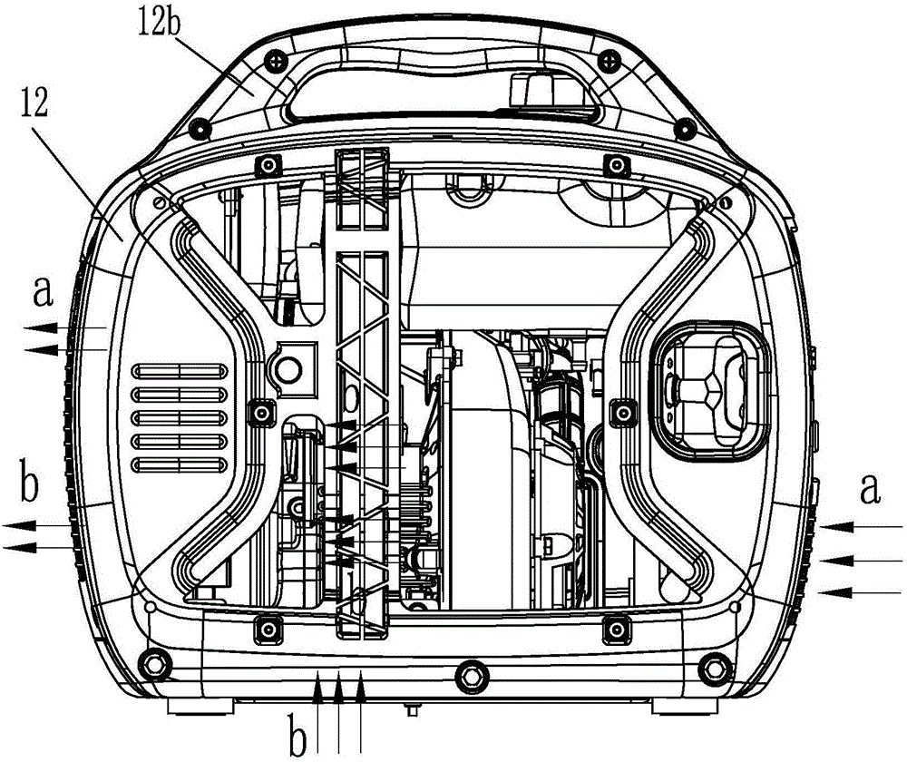
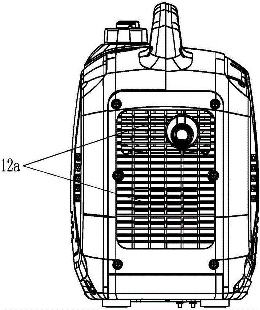
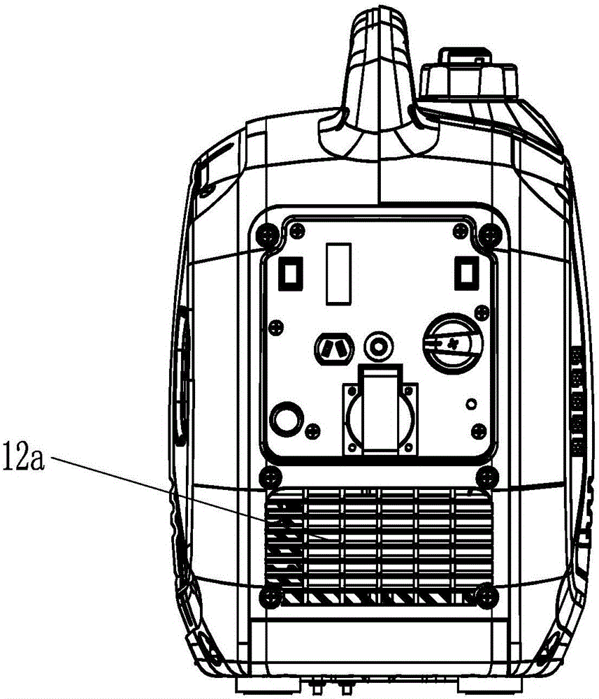
[0023] Such as figure 1 The generator set shown includes a set casing 12 , an engine generator set in the set casing 12 , and besides, an inverter set in the set casing 12 .

[0024] to combine Figure 4 — Figure 8 The engine type generator shown is mainly composed of a cylinder head 1, a muffler 2, a motor 3, a starter 4 (including a starter pull plate 4a and a starter wind guide 4b), a cylinder head wind guide 5, a muffler cover 6, The muffler air outlet rubber sleeve 7, the engine case cover 8, the cooling fan 9, the air filter 10, the motor end cover 11 and the like are composed.

[0025] There are two cooling air passages in the engine generator, one is the engine cooling air passage a for cooling the cylinder head 1 and the muffler 2, and the other is for cooling the motor 3. Motor cooling duct b.

[0026] The air inlet of the engine cooling a...


PUM


Abstract

The invention discloses an efficient generator unit with two cooling air ducts. The efficient generator unit with the two cooling air ducts comprises a unit shell and an engine type generator. The engine type generator comprises an engine cooling air channel and a motor cooling air channel. An air inlet of the engine cooling air channel is formed in a starter pull disk. An air outlet of the engine cooling air channel is formed in a muffler air outlet rubber cover. A cylinder head and a muffler are arranged in a closed channel formed between the air inlet and the air outlet of the engine cooling air channel. Air inlets of the motor cooling air channel are formed in the top, the side face and the bottom of an engine case cover respectively. An air outlet of the motor cooling air channel is formed in a motor end cover. A cooling fan and a motor are arranged in a closed channel formed between the air inlets and the air outlet of the motor cooling air channel. Blades of the cooling fan are of an arc-shaped cover structure. The two cooling air channels are independent of each other, so that the air channels is simplified, arrangement of the air channels is optimized, and the number of parts is reduced; the blades of the cooling fan are of the arc-shaped cover structure, so the air supply amount is increased, and the cooling effect of the generator is improved jointly.

Description

technical field [0001] The invention relates to the technical field of generator sets, in particular to the structure of a cooling air passage in an engine generator set. Background technique [0002] The engine-type generator runs the motor through the engine to generate electricity. The engine-type generator is equipped with an engine cooling air duct and a motor cooling air duct. Cool down. [0003] In the existing engine-type generators, there are mainly two structural forms: one is that the two cooling air channels respectively cool the cylinder head and the motor, and then cool the muffler together after converging. This structure ensures smooth flow of the cooling air, and the cooling air The channel structure is complex, the number of parts constituting the cooling air channel is large, and the installation accuracy is very high; the other is to cool the cylinder head first, and then divide it into two channels to cool the muffler and the motor respectively, but the...

Claims


Application Information

Patent Timeline
Patent Type & Authority Applications(China)
IPC IPC(8): F02B63/04F01P1/00F01P5/02F16M1/00F04D29/26
CPCF01P5/02F01P5/06F02B63/04
Inventor 谢安源秦尚勇黄飞
Owner CHONGQING AMPRIDE POWER & MACHINERY
Why Eureka
Try Eureka