

Nano-film air purification window
An air purifying window and nano-film technology, applied in the direction of windows/doors, chemical instruments and methods, special equipment for doors/windows, etc. , easy to use effect
- Summary
- Abstract
- Description
- Claims
- Application Information
AI Technical Summary
Problems solved by technology
Method used
Image

Examples
Embodiment 1
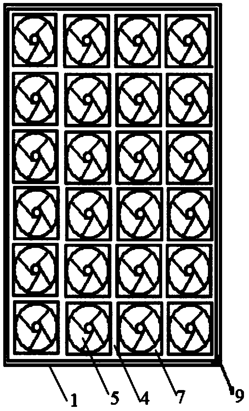
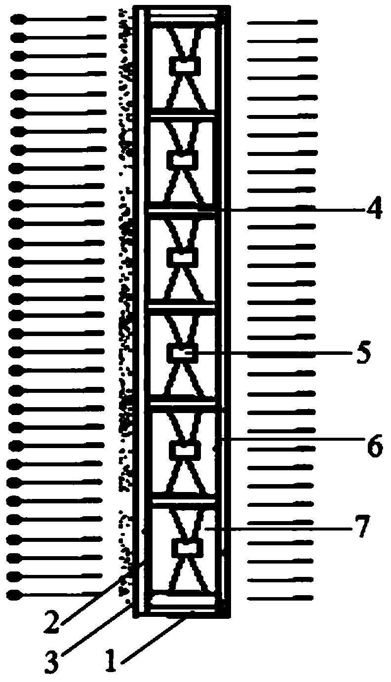
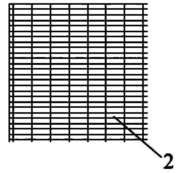
[0029] like figure 1 and figure 2 As shown, the side of the purification window in contact with the outdoor air is the outer side, and the side in contact with the indoor air is the inner side. The upper and outer sides of the window frame 1 are provided with a support net 2. The support net 2 is a braided wire mesh structure. The structure of the support net 2 is as follows: image 3 As shown, the support net 2 is covered with a polytetrafluoroethylene (PTFE) nano-membrane filter layer 3 with a pore size of 0.1-2.5 μm. The support net 2 and the nano-membrane filter layer 3 are bonded and connected to the edge of the window frame 1. Due to its small thickness, the nano-membrane filter layer 3 is easily deformed and ruptured when the air velocity it passes through is fast. The support net 2 can effectively maintain its shape for a long time and prolong its service life.
[0030] The inner side of the window frame 1 is provided with a plurality of partitions 4, and the ends o...
Embodiment 2
[0033] In this embodiment, the structures of the window frame 1, the support net 2, and the nano-membrane filter layer 3 are all the same as those of the embodiment 1, and will not be repeated here. The structure of miniature air intake fan 5 is as Figure 6-8 As shown, there are connecting flanges 10 around the shell of the miniature air intake fan 5, and buckles 11 are provided on the inner walls of the connecting flanges 10 on each side. The buckles 11 are V-shaped structures made of elastic materials, wherein the V-shaped structure One end is fixed on the inner wall of the connecting flange 10. The connecting flange 10 covers the partition 4 around the space 7, and the partition 4 is provided with a rectangular connection hole 12 matched with the buckle 11. The length of the connection hole 12 is less than the distance between the open ends of the V-shaped structure in the buckle 11. The cell structure formed by the criss-cross distribution of separators 4 is as follows: ...
PUM
| Property | Measurement | Unit |
|---|---|---|
| Power | aaaaa | aaaaa |
| Aperture | aaaaa | aaaaa |
Abstract
Description
Claims
Application Information