Bent U-shaped box shell bending and splicing structure

A box shell and splicing angle technology, which is applied in lighting and heating equipment, household appliances, household refrigeration devices, etc., can solve the problems that affect the appearance of the box shell and production efficiency, require high precision of the splicing structure, and easily form burrs, etc. Achieve the effect of reducing the market and inspection complaint rate, facilitating processing and adjustment, and reducing sharp corners

Inactive Publication Date: 2015-10-28
HEFEI HUALING CO LTD +1
View PDF6 Cites 1 Cited by
  • Summary
  • Abstract
  • Description
  • Claims
  • Application Information

AI Technical Summary

Problems solved by technology

[0002] The existing refrigerator box shell is provided with a U-shaped structure at the edge joint of the 45-degree angle (that is, at the edge joint of the box shell sheet metal parts, the U-shaped structure formed by bending the sheet metal edge at least twice is also called a U-shaped structure. case), with figure 1 It is an expansion diagram of a common U-shaped structure, with figure 2 It is a schematic diagram after bending. Usually the structure is complex. The punching die is easy to form burrs when punching the sheet metal parts, and the precision of the splicing structure is high. Form a sharp angle, if it is greater than 0.5mm, it will form an obvious dislocation, which will affect the appearance of the box shell and the efficiency of production

Method used


Image

  • Bent U-shaped box shell bending and splicing structure
  • Bent U-shaped box shell bending and splicing structure
  • Bent U-shaped box shell bending and splicing structure

Examples


Embodiment Construction

[0029] The principles and features of the present invention are described below in conjunction with the accompanying drawings, and the examples given are only used to explain the present invention, and are not intended to limit the scope of the present invention.

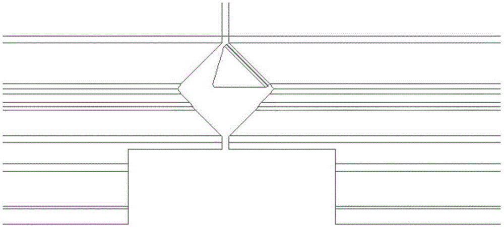
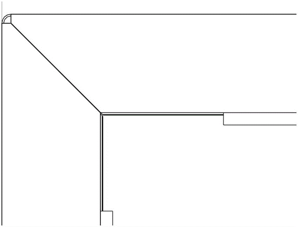
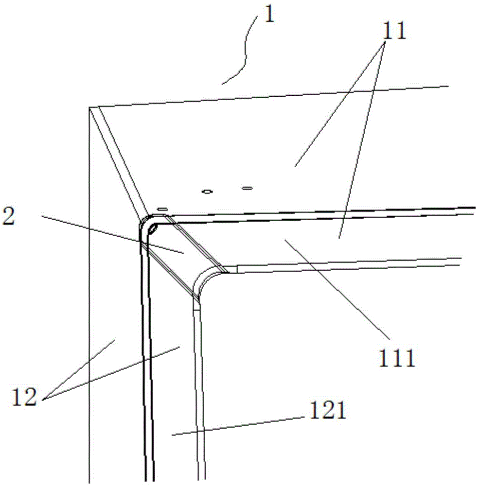
[0030] Such as image 3 As shown, a U-shaped box shell bending splicing structure, the U-shaped box shell includes a first spliced ​​plate 11 with a first folded edge 111 and a second spliced ​​plate 12 with a second folded edge 121, the first spliced The plate 11 and the second splicing plate 12 are spliced ​​to form a splicing angle structure 1, and one end of the first folded edge 111 and the second folded edge 121 is provided with a 45-degree spliced ​​edge, and the first folded edge 111 and the second folded edge 121 Through the splicing of the 45-degree splicing edge, the splicing part is provided with a cover 2 detachably connected to the first folded edge 111 and the second folded edge 121 .

[0031] Prefer...


PUM


Abstract

The invention relates to a bent U-shaped box shell bending and splicing structure. The structure comprises a first splicing plate with a first folded edge and a second splicing plate with a second folded edge. The first splicing plate and the second splicing plate are spliced to form a spliced corner structure. One end of the first folded edge and one end of the second folded edge are each provided with a 45-degree splicing edge. The first folded edge and the second folded edge are spliced through the 45-degree splicing edges. The spliced part is provided with a covering element capable of being detachably connected with the first folded edge and the second folded edge. Sharp corners, burrs, malposition and other problems caused by insufficient strength or insufficient punching precision of a punching die can be reduced. Besides, the structure is attractive after splicing, and the surface of a box shell is clean. Cut corners, smaller than 2 mm, of the punching die can be eliminated and optimized, and reliability of the punching die is improved. The splicing structure is simple, consistency is good in the production process, the yield is high, and the market and inspection complaint rate is reduced.

Description

technical field [0001] The invention relates to the field of splicing structure of refrigerator box shells, in particular to a bending splicing structure of U-shaped box shells. Background technique [0002] The existing refrigerator box shell is provided with a U-shaped structure at the edge joint of the 45-degree angle (that is, at the edge joint of the box shell sheet metal parts, the U-shaped structure formed by bending the sheet metal edge at least twice is also called a U-shaped structure. case), with figure 1 It is an expansion diagram of a common U-shaped structure, with figure 2 It is a schematic diagram after bending. Usually the structure is complex. The punching die is easy to form burrs when punching the sheet metal parts, and the precision of the splicing structure is high. A sharp angle is formed, and if it is greater than 0.5mm, an obvious dislocation will be formed, which will affect the appearance of the box shell and the efficiency of production. Cont...

Claims


Application Information

Patent Timeline
Patent Type & Authority Applications(China)
IPC IPC(8): F25D23/06
CPCF25D23/06
Inventor 赵艳锋
Owner HEFEI HUALING CO LTD
Why Eureka
Try Eureka