Light splitting module and laser demarcation device provided with light splitting module

A light splitting module, light technology

Active Publication Date: 2015-10-28
CHANGZHOU HUADA KEJIE OPTO ELECTRO INSTR
View PDF5 Cites 9 Cited by
  • Summary
  • Abstract
  • Description
  • Claims
  • Application Information

AI Technical Summary

Problems solved by technology

It is precisely because of the manual fine-tuning work in design and installation that brings many precision problems to optoelectronic instruments
[0003] At the same time, when the emission requirements for optoelectronic instruments become more and more complex, the number of laser tubes will also increase accordingly. Too many laser tubes will lead to relatively larger optoelectronic instruments, accompanied by higher assembly costs, which is not conducive to the miniaturization of optoelectronic instruments develop

Method used


Image

  • Light splitting module and laser demarcation device provided with light splitting module

Examples


Embodiment Construction

[0019] The advantages of the present invention will be further elaborated below in conjunction with the accompanying drawings and specific embodiments.

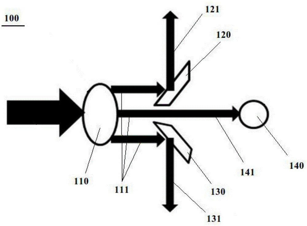
[0020] refer to figure 1 , in the present invention, in order to produce the light distribution mode of a plurality of outgoing light to single light source, in the light outlet of a laser emitting device (not shown), be provided with a splitting module 100, wherein this splitting module 100 comprises:

[0021] -focusing lens 110, arranged on the light outlet of the laser emitting device, the laser light generated by the laser emitting device is focused by the focusing lens 110 to remove stray light and generate parallel rays, and the laser generated by the laser emitting device passes through the focusing lens 110 , an outgoing convergent light 111 is generated by the focusing lens 110;

[0022] - The first reflecting mirror 120 and the second reflecting mirror 130 are disposed behind the focusing lens 110 and on the optica...


PUM


Abstract

The invention provides a light splitting module. The light splitting module is arranged at a light outlet of a laser emitting device. The light splitting module comprises a focusing lens which is arranged at the light outlet of the laser emitting device and used for focusing the laser emitted by the laser emitting device; a first reflecting mirror and a second reflecting mirror which are arranged on the light path of converged light and used for respectively reflecting lasers on two sides of the converged light so as to shaping the converged light into first reflected light, second reflected light and central light, wherein the first reflected light and the second reflected light are reflected to two sides, and the central light is arranged at the middle part of the converged light; a cylindrical mirror which is arranged on the path of the central light, wherein the central light penetrates through the cylindrical mirror to form laser light. The invention further provides a laser demarcation device provided with the light splitting module. By adopting the above technical scheme, projection in a single-light source two-point one-line manner is realized by a simple structure; in addition, according to different light distribution requirements, different light distribution schemes can be obtained by means of combination, and the design of the laser demarcation is simplified.

Description

technical field [0001] The invention relates to the field of photoelectric instruments, in particular to a spectroscopic module and a laser line projector with the spectroscopic module. Background technique [0002] The original spectroscopic technology in the field of optoelectronic instruments requires the pendulum to have multiple laser tubes with different angles. When it is necessary to produce a certain light distribution, the light output angle of the laser tubes should be adjusted according to the requirements. In addition, during the assembly process of photoelectric instruments, the laser tube needs to be adjusted so that the emitted beam lines or points meet the requirements in a vertical or horizontal state. It is precisely because more manual fine-tuning operations in design and installation have brought many precision problems to optoelectronic instruments. [0003] At the same time, when the emission requirements for optoelectronic instruments become more and...

Claims


Application Information

Patent Timeline
IPC IPC(8): G02B27/10G01C15/00
CPCG01C15/00G02B27/10
Inventor 张瓯徐臣
Owner CHANGZHOU HUADA KEJIE OPTO ELECTRO INSTR
Why Eureka
Try Eureka