Check patentability & draft patents in minutes with Patsnap Eureka AI!

Conductive belt, conductive rod mechanism and isolating switch using the same

A technology of conductive strips and conductive rods, applied in the fields of conductive rod mechanisms, conductive strips, and isolation switches, can solve the problems of hindering the swinging action of the conductive rods, large swing resistance of the conductive rods, and large heat generation, etc., to improve the heat dissipation effect and the heat dissipation effect. Good, the effect of reducing heat generation

Active Publication Date: 2017-10-27
PINGGAO GRP +2
View PDF1 Cites 0 Cited by
  • Summary
  • Abstract
  • Description
  • Claims
  • Application Information

AI Technical Summary

Problems solved by technology

However, as the capacity of the isolating switch increases, the thickness of the conductive strip also needs to increase accordingly. At this time, the number of layers of aluminum foil in the conductive strip will also increase accordingly. As far as the single-layer aluminum foil is concerned, it is affected by a small thickness. , the resistance of a single layer of aluminum foil is relatively large, which increases the total calorific value of each layer of aluminum foil in the entire conductive strip, and the gap between each layer of aluminum foil is very small, so it often occurs in the conductive rod mechanism of the disconnector The defects of poor flow performance and high heat generation increase the consumption of electric energy between the conductive rod and the terminal block
And if the conductive strip is replaced with an integral strip body, limited by the rigidity of the strip itself, the conductive strip will hinder the swinging action of the conductive rod, so that the swing resistance of the conductive rod is too large

Method used


Image

  • Conductive belt, conductive rod mechanism and isolating switch using the same
  • Conductive belt, conductive rod mechanism and isolating switch using the same

Examples


Embodiment Construction

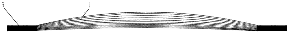
[0021] The embodiment of isolating switch among the present invention: as figure 1 and figure 2 As shown, the isolating switch is a neutral bus isolating switch for capacity enhancement. The main structure of the isolating switch is the same as that of the existing common isolating switch. The main improvement lies in the conductive strip between the conductive rod and the terminal block in the conductive rod mechanism. , the conductive strip can be applied in the field of high-voltage switchgear and high-voltage electrical appliance manufacturing, and on the neutral bus DC isolating switch of the DC converter station. It is mainly used for the main conductive part of the isolating switch to connect the external wiring and the main conductive fracture.

[0022] The conductive strip is composed of a strip body 1 and a tin-coating layer 5 arranged at both ends thereof, such as figure 1 As shown, the lower side of the strip body 1 is the concave side that is always inwardly sun...


PUM


Abstract

The invention discloses a conductive band, and a conductive rod mechanism and an isolating switch using the conductive band. The conductive band comprises a band body which is composed of layers of substrates, wherein the substrates positioned at the inward concave side is thicker than the substrates positioned at the outward convex side. Thus, under the circumstance that the total thickness of the band body is kept unchanged, the total number of layers of substrates in the band body of the conductive band provided by the invention can be reduced accordingly when compared with equal-thickness substrates in the prior art, thereby the number of heat sources in the band body is reduced, the heat productivity of the whole band body is reduced accordingly, and the radiating effect is improved; in addition, since the thickened substrates are positioned at the inward concave side of the layers of substrates, the expansion and contraction amplitude of the substrates at the inward concave side during the swinging process of the conductive rod is small when compared with that of the substrates at the outward convex side, that is, though thickness of part of the substrates is increased, the thickened substrates cannot cause excessive impact on the swing of the conductive rod, and thus the conductive rod can swing normally.

Description

technical field [0001] The invention relates to a conductive belt, a conductive rod mechanism and a disconnector using the conductive belt. Background technique [0002] At present, the State Grid Corporation of China has proposed in the "Twelfth Five-Year Plan" that in the future, my country will build a "three vertical and three horizontal" UHV backbone grids and 13 direct current transmission projects connecting large energy bases and main load centers, forming a large-scale " The energy allocation pattern of "West-to-East Power Transmission" and "North-to-South Power Transmission". UHV DC asynchronous networking can meet the requirements of long-distance and large-capacity power transmission, and there is no need to provide power support along the line. Through UHV networking, the power exchange capability of the network can be enhanced, and the allocation of energy resources can be optimized in a wider range. In order to better allocate energy resources, for direct cur...

Claims


Application Information

Patent Timeline
Patent Type & Authority Patents(China)
IPC IPC(8): H01H31/02H01H1/58
CPCH01H1/58H01H31/023
Inventor 熊萍萍胡延涛张友鹏程铁汉仝永刚孙珂珂马志华门博朱继斌
Owner PINGGAO GRP
Features
  • R&D
  • Intellectual Property
  • Life Sciences
  • Materials
  • Tech Scout
  • Unparalleled Data Quality
  • Higher Quality Content
  • 60% Fewer Hallucinations
Learn More