Planetary gear deceleration integrated motor

A planetary gear reduction and planetary gear technology, applied in the field of integrated motors, can solve the problems of high manufacturing cost, poor reliability, complex structure, etc., and achieve the effects of high manufacturing cost, low cost and high transmission efficiency

Inactive Publication Date: 2015-10-28
张思强
View PDF5 Cites 12 Cited by
  • Summary
  • Abstract
  • Description
  • Claims
  • Application Information

AI Technical Summary

Problems solved by technology

However, due to defects such as complex structure, poor reliability, and high manufacturing cost, it cannot compete with hub motors in the market

Method used


Image

  • Planetary gear deceleration integrated motor
  • Planetary gear deceleration integrated motor
  • Planetary gear deceleration integrated motor

Examples


Embodiment Construction

[0022] Below by embodiment and in conjunction with accompanying drawing, the present invention will be further described:

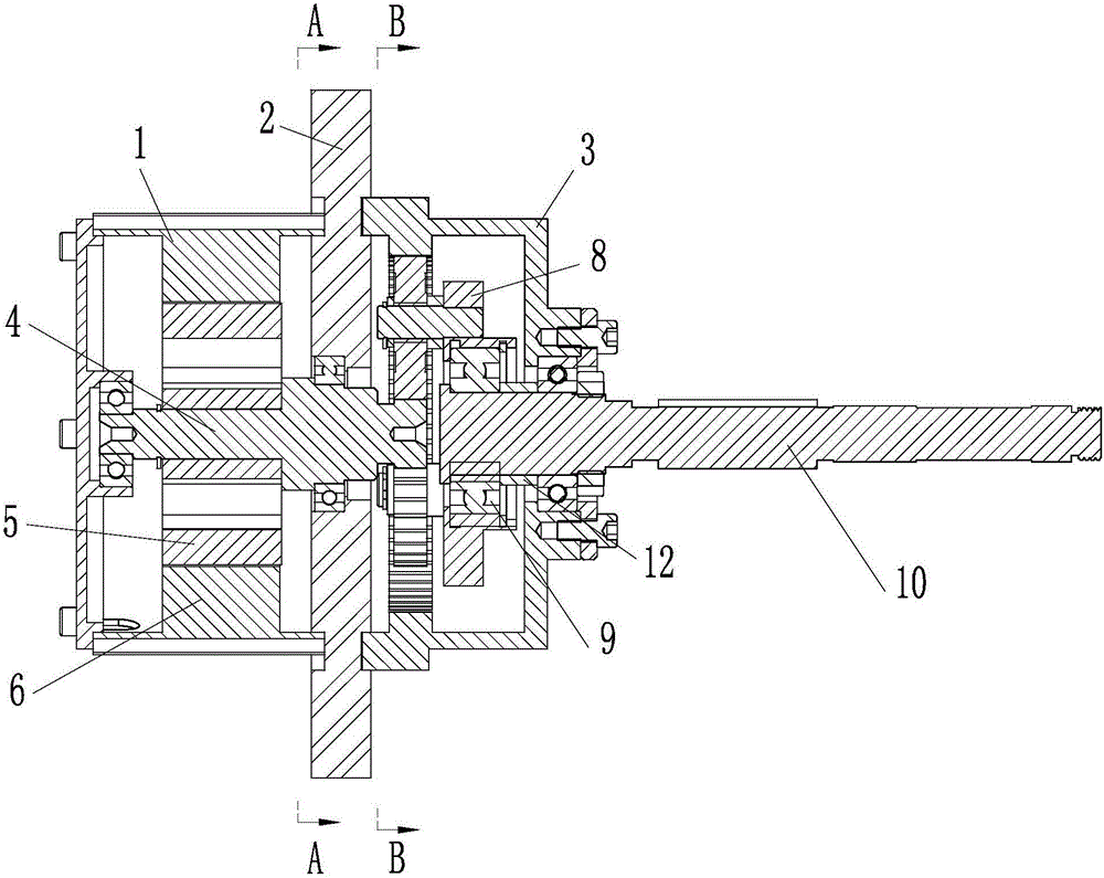
[0023] combine figure 1 — image 3 As shown, a planetary gear reduction integrated motor is mainly composed of a housing part, a motor part and a planetary gear reduction part.

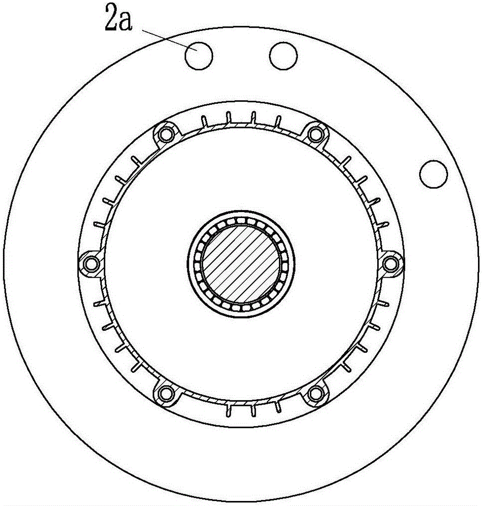
[0024] The shell part is composed of three parts, the motor shell 1, the main beam plate 2 and the reduction box shell 3, which are connected in sequence. The main beam plate 2 is provided with a motor installation hole 2a for the installation of the entire motor.

[0025] The motor part is installed in the cavity surrounded by the motor housing 1 and the main beam plate 2 through bearings, and the motor part is mainly composed of a rotor shaft 4 , a motor rotor 5 and a motor stator 6 .

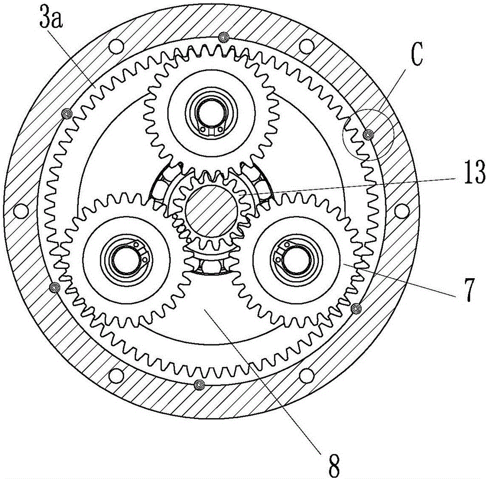
[0026] The planetary gear reduction part is installed in the cavity surrounded by the reduction box housing 3 and the main beam plate 2 through bearings. The planetary gear reduction part is ...


PUM


Abstract

Disclosed in the invention is a planetary gear deceleration integrated motor comprising a housing part, a motor part, and a planetary gear deceleration part. The housing part consists of a motor shell, a main beam plate, and a reduction gearbox shell. The motor part installed in a cavity encircled by the motor shell and the main beam plate by a bearing contains a rotor shaft, a motor rotor, and a motor stator. The planetary gear deceleration installed in a cavity encircled by the reduction gearbox shell and the main beam plate by a bearing includes a sun wheel, a planet wheel, a planet carrier, an overturning clutch, and a power output shaft; the rotator shaft extends into the reduction gearbox shell to drive the sun wheel to make rotation; the sun wheel drives the planet wheel to rotate; the planet wheel drive the planet carrier to make rotation; the overturning clutch sleeves the power output shaft; the planet carrier drives the power output shaft to make rotation by the overturning clutch; and an annular gear arranged in the reduction gearbox shell is engaged with the planet wheel. The motor has advantages of small size, light weight, simple structure, high transmission efficiency, and low manufacturing cost.

Description

technical field [0001] The invention belongs to the technical field of drive motors, and in particular relates to an integrated motor integrated with a planetary gear reduction mechanism, which is mainly used in the fields of electric bicycles and electric motorcycles to provide power sources for them. Background technique [0002] Most of the power sources of today's electric bicycles and electric motorcycles use hub motors. Since the rotor and the wheel are integrated in the in-wheel motor, the motor is destined to be a low-speed motor (rotor speed n<600rpm). Because it is a low-speed motor, under the condition of a certain motor quality, the torque that can be provided is small, which is manifested in the vehicle, that is, the vehicle's climbing ability is weak, and it is difficult to meet the driving requirements of the slope road surface; It is used under various road conditions and traffic conditions. During the driving process of the vehicle, the speed of the vehi...

Claims


Application Information

Patent Timeline
Patent Type & Authority Applications(China)
IPC IPC(8): H02K7/116
Inventor 王乃奎张思强
Owner 张思强
Why Eureka
Try Eureka