
Lubricating oil injecting device for electric equipment

A technology of electric power equipment and lubricating oil, applied in the field of electric power, can solve the problems of affecting the service life of switches, knife switches and other equipment, affecting the reliability of power supply, and hidden dangers of staff safety, so as to improve the reliability of power supply and avoid work flow and Mode adjustment, the effect of reducing labor intensity

Inactive Publication Date: 2015-11-04
TAIAN POWER SUPPLY CO OF STATE GRID SHANDONG ELECTRIC POWER CO +2
View PDF6 Cites 4 Cited by
  • Summary
  • Abstract
  • Description
  • Claims
  • Application Information

AI Technical Summary

Problems solved by technology

[0003] 1. Increase the number of power outages, frequent operation will affect the service life of switches, knife switches and other equipment, and affect the reliability of power supply
[0004] 2. Climbing operations can easily bring safety hazards to the staff
[0005] 3. Work tickets need to be processed for power outage operations, and scheduling applications are required. The process is complicated and brings more unnecessary troubles

Method used


Image

  • Lubricating oil injecting device for electric equipment
  • Lubricating oil injecting device for electric equipment

Examples


Embodiment Construction

[0024] Typical embodiments embodying the features and advantages of the present invention will be described in detail in the following description. It should be understood that the invention is capable of various changes in different embodiments without departing from the scope of the invention, and that the description and illustrations therein are illustrative in nature and not limiting. this invention.

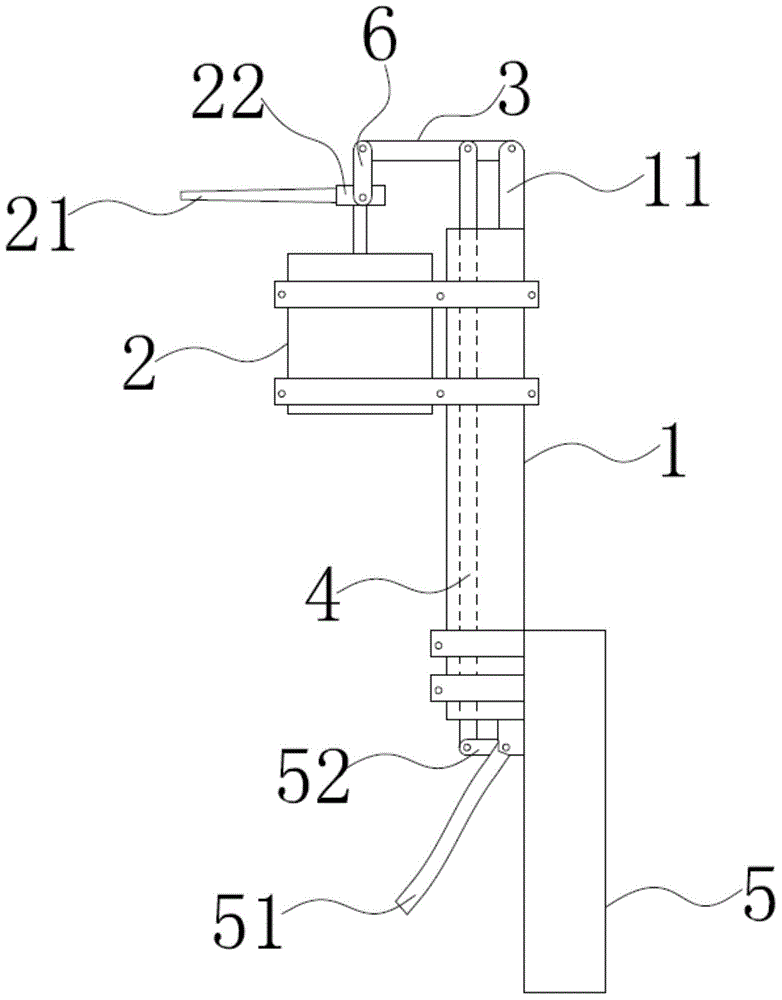
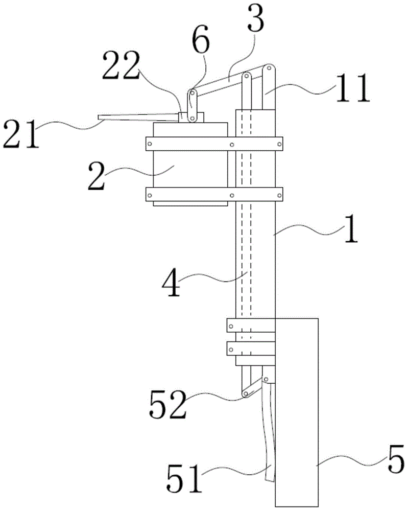
[0025] Such as figure 1 and figure 2 As shown, the present invention provides a lubricating oil filler for electric equipment, including an operating rod 1, an oil filling bottle 2, a first control connecting rod 3 and a second control connecting rod 4; wherein, an accommodation space is formed inside the operating rod 1 , a part of the second control link 4 can be movably installed in the accommodating space, the operating rod 1 has two ends, one end is a mounting part, and the other end is a handle part;

[0026] The oil filling bottle 2 is detachably installed on the...


PUM


Abstract

A lubricating oil injecting device for electric equipment comprises an operating rod, an oil injection bottle, a first control connection rod and a second control connection rod. Two ends are arranged on the operating rod. One end is an installing part, and the other end is a handheld part. The oil injection bottle is detachably installed on the installing part of the operating rod and parallel to the operating rod. The oil injection bottle is provided with an oil injection valve and an oil injection nozzle. The interior and the exterior of the oil injection bottle are communicated through the oil injection valve. The oil injection nozzle is communicated with the oil injection bottle through the oil injection valve. The first control connection rod is transversely arranged above the oil injection bottle. One end of the first control connection rod is connected with the top end of the installing part of the operating rod in a pivoted mode, and the other end of the first control connection rod is arranged over the oil injection valve. The second control connection rod is arranged between the oil injection bottle and the operating rod. One end of the second control connection rod is connected to the first control connection rod, and the other end of the second control connection rod extends to the bottom end of the oil injection bottle. When the second control connection rod is pulled downwards, the first control connection rod is driven to move downwards and abut the oil injection valve, and the oil injection valve makes lubricating oil in the oil injection bottle sprayed out through the oil injection nozzle under the pressure of the first control connection rod; and the lubricating oil injecting device is safe and capable of saving oil and greatly improves work efficiency.

Description

technical field [0001] The invention relates to the field of electric power, in particular to a lubricating oil filler for electric power equipment. Background technique [0002] At present, during the daily maintenance of substations or other electrical equipment, especially some mechanical mechanisms are prone to problems such as jamming and corrosion, which seriously affect the normal mechanical transmission of the equipment, and it is necessary to add lubricating oil to the transmission parts. The traditional method is to deal with power outage climbing, but the traditional method has the following three defects: [0003] 1. Increase the number of power outages, frequent operation will affect the service life of switches, knife switches and other equipment, and affect the reliability of power supply. [0004] 2. Climbing operations can easily bring safety hazards to the staff. [0005] 3. Work tickets and scheduling applications are required for power outage operations...

Claims


Application Information

Patent Timeline
Patent Type & Authority Applications(China)
IPC IPC(8): F16N3/04
Inventor 陈胜李亚平张国施卫东张振郑鹏宿波刘昂
Owner TAIAN POWER SUPPLY CO OF STATE GRID SHANDONG ELECTRIC POWER CO
Learn More