
A Quantitative Analysis Method for the Heavy Ion Single Event Multi-Position Flip Effect of Devices

A technology of multi-bit flipping effect and single-particle flipping, which is applied in the fields of instruments, special data processing applications, and electrical digital data processing, etc. Problems such as lack of clear understanding of the representation of bit flips

Active Publication Date: 2018-01-19
NORTHWEST INST OF NUCLEAR TECH
View PDF6 Cites 0 Cited by
  • Summary
  • Abstract
  • Description
  • Claims
  • Application Information

AI Technical Summary

Problems solved by technology

Usually, when carrying out the device single event effect test, the test system measures and obtains the single event flip test data based on the logical address, so it cannot objectively reflect whether the memory cells where the single event flip occurs are physically adjacent and whether they can be judged as real single event multiple bit flip
On the other hand, even if the physical bitmap of the device is obtained, and the mapping from the logical address to the physical address of the single event flip is established, the selection of the ion fluence rate is not controlled in the effect test, and the conventional single event effect test method is selected. Flux rate range 10 2 -10 5 / cm 2 Any fluence rate between .s is easy to introduce "false" multi-bit flips caused by different particles incident at adjacent physical positions, resulting in excessive statistical errors of single-particle multi-bit flips
At the same time, there is a lack of clear understanding of the characterization of single-event multi-bit flipping, resulting in the definition and calculation of multi-bit flipping not being able to accurately and effectively reflect the sensitivity of devices to single-event multi-bit flipping

Method used


Image

  • A Quantitative Analysis Method for the Heavy Ion Single Event Multi-Position Flip Effect of Devices
  • A Quantitative Analysis Method for the Heavy Ion Single Event Multi-Position Flip Effect of Devices
  • A Quantitative Analysis Method for the Heavy Ion Single Event Multi-Position Flip Effect of Devices

Examples


Embodiment Construction

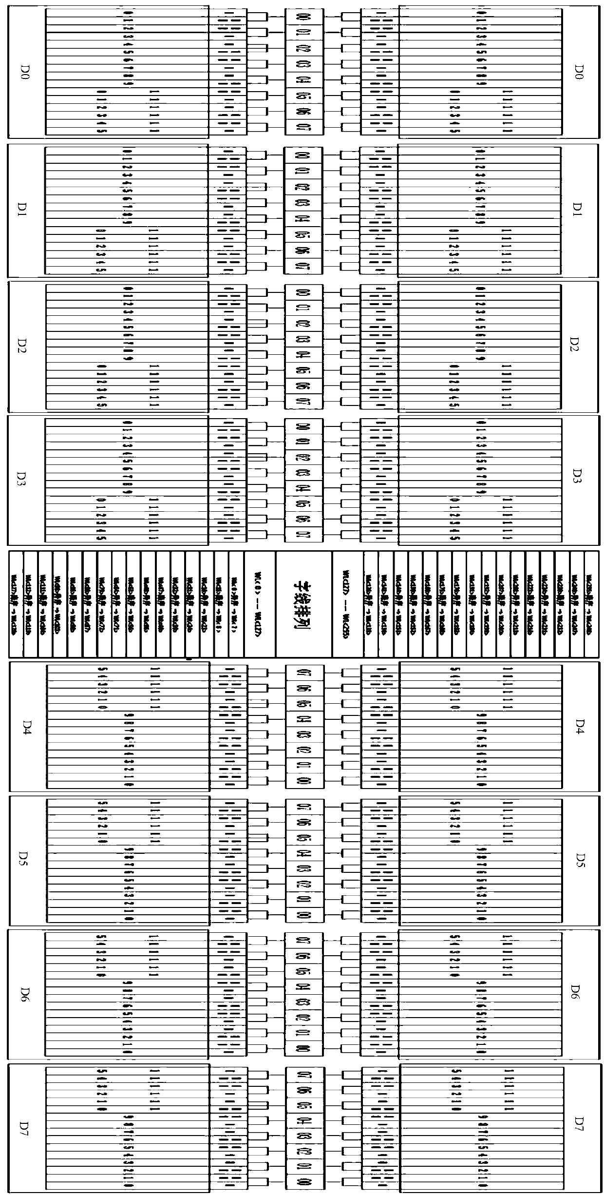
[0060] Taking a certain static memory H328X circuit as an example, the specific implementation of the present invention will be described in detail in conjunction with the accompanying drawings. H328X is a synchronous single-port SRAM circuit with a storage capacity of 32K×8 bits and a total of 256Kbit. The following examples are only used to illustrate the present invention. , but not to limit the scope of the present invention.

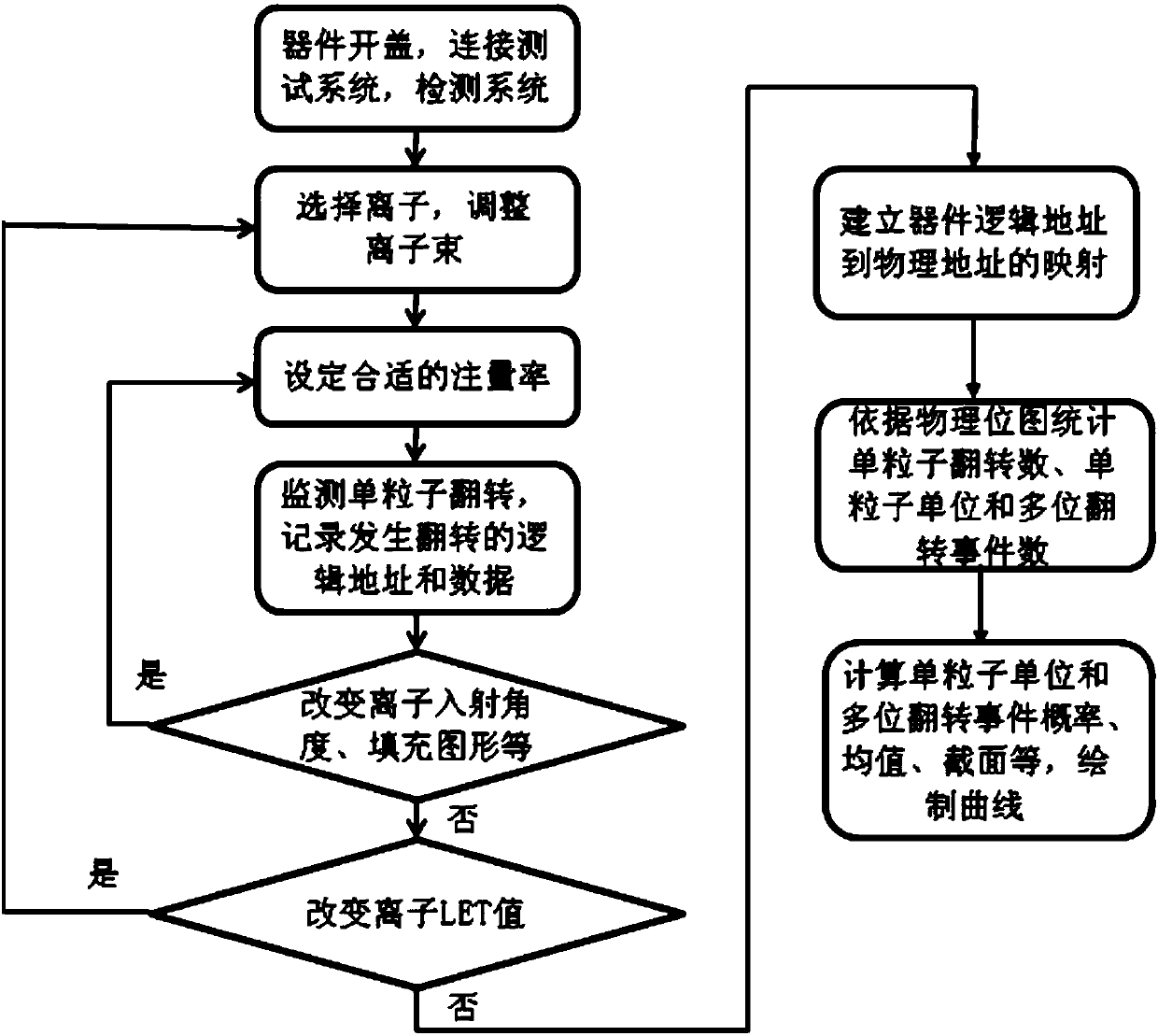
[0061] figure 1 It is a flow chart of the quantitative analysis method for the heavy ion single event multi-position flipping effect of the device of the embodiment of the present invention, combined with figure 1 , to describe this method in detail.

[0062] (1) Before the test, the sample is opened and the functional parameters are tested. After the test is passed, the sample is inserted on the PCB irradiation board, fixed at the test position by the sample holder, and aligned and positioned. Connect the test system, power supply circuit and PCB...


PUM


Abstract

The invention discloses a quantitative analysis method for the heavy ion single particle multi-position flipping effect of a device. The method includes: selecting the type of heavy ion, setting a suitable fluence rate according to the corresponding principle to irradiate the device with the cover opened, and testing the system Record the logic address and data of the storage unit where the single event flip occurs in the device, and stop the irradiation when the expected number of single event flips or the maximum ion fluence is reached. Establish the mapping relationship from the logical address of the device to the physical address, and count the number of single-event flips, single-event unit flips, and multi-bit flip events based on the physical bitmap. Combined with the ion fluence, calculate the event probability of single event unit flipping and multibit flipping, the average value of multibit flipping, the cross section of multibit flipping and other parameters. The invention can provide technical support and information for the anti-single event flipping reinforcement design of the device, and verify and evaluate the effectiveness of the reinforcement technology.

Description

technical field [0001] The invention relates to a quantitative analysis method for the heavy ion single particle multi-position flip effect of a device, and belongs to the research field of space single particle effect ground simulation test technology and reinforcement technology. Background technique [0002] With the continuous improvement of the performance requirements of large-scale integrated circuits in satellite electronic systems, the use of ultra-deep submicron and nanoscale integrated circuits has become an inevitable development trend. The primary problem brought about by the reduction of the device feature process size is the reduction of the critical charge. The critical charge is the minimum charge required for the device to undergo a single-event flip. It is inversely proportional to the square of the process size. In this case, the critical charge of the device is already less than 2fC. This means that after high-energy particles enter the device, the ioni...

Claims


Application Information

Patent Timeline
Patent Type & Authority Patents(China)
IPC IPC(8): G06F17/50
Inventor 罗尹虹张凤祁郭红霞陈伟王忠明赵雯丁李利王园明
Owner NORTHWEST INST OF NUCLEAR TECH
Learn More