Supercharge Your Innovation With Domain-Expert AI Agents!

An integrated system of drive motor and transmission for electric vehicles

A technology for driving motors and electric vehicles, applied in the field of integrated systems, can solve the problems of increasing system weight and production costs, affecting the installation structure of the whole vehicle, and long axial dimensions, and achieves simple structure, optimized installation structure, and fewer parts and components. Effect

Active Publication Date: 2017-07-28
上海汽车电驱动有限公司 +1
View PDF5 Cites 0 Cited by
  • Summary
  • Abstract
  • Description
  • Claims
  • Application Information

AI Technical Summary

Problems solved by technology

[0004] The integrated system of the drive motor and the transmission of the existing electric vehicle includes a drive motor and a transmission. The drive motor includes a rotating shaft, a rotor assembly, a stator assembly, a casing, a front end cover and a rear end cover, and the rotor assembly is installed on the rotating shaft. The assembly is connected with the casing and nested outside the rotor assembly. The front end cover and the rear end cover are respectively installed at both ends of the casing. The rotating shaft is supported on the bearings of the front end cover and the rear end cover. The rear end cover is connected together, and the rotating shaft of the motor and the rotating shaft of the transmission are installed together through internal splines and external splines. However, this integrated system has the following problems: 1) The axial dimension of the system is long, which affects the entire vehicle. 2) There are many components, which leads to low production efficiency and increases the weight and production cost of the system

Method used


Image

  • An integrated system of drive motor and transmission for electric vehicles
  • An integrated system of drive motor and transmission for electric vehicles
  • An integrated system of drive motor and transmission for electric vehicles

Examples


Embodiment Construction

[0020] The present invention will be described in further detail below through specific embodiments and in conjunction with the accompanying drawings.

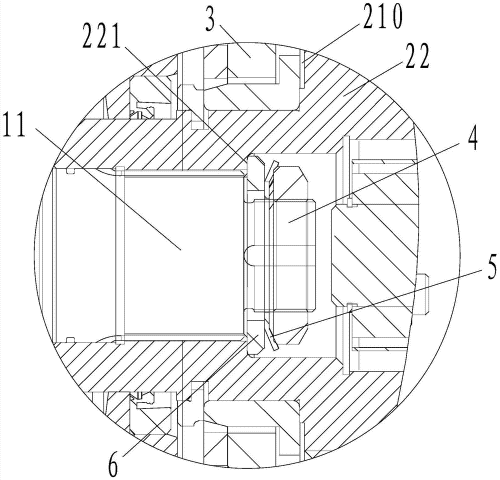
[0021] Such as figure 1 , figure 2 with image 3 As shown, the present invention is an integrated system of a drive motor and a transmission of an electric vehicle, including a drive motor 1 and a transmission 2, and the drive motor 1 includes a motor shaft 11, a rotor assembly 12, a stator assembly 13 and a casing 14, The rotor assembly 12 is installed on the rotating shaft 11, the stator assembly 13 and the casing 14 are installed together and nested outside the rotor assembly 12, the transmission 2 mainly includes a front end cover 21 and a transmission rotating shaft 22, and a bearing chamber 210 is arranged in the middle of the front end cover 21. Bearing 3 is installed in bearing chamber 210 inside, and the input end of speed changer rotating shaft 22 is supported on the bearing 3 of front end cover 21, and the front ...


PUM


Abstract

An integrated system of a drive motor and a transmission for an electric vehicle, comprising a drive motor (1) and a transmission (2). The drive motor (1) comprises a motor rotation shaft (11), a rotor assembly (12), a stator assembly (13), and a housing (14). The rotor assembly (12) is mounted on the rotation shaft (11). The stator assembly (13) and the housing (14) are mounted together and are nested outside the rotor assembly (12). The transmission (2) mainly comprises a front end cover (21) and a transmission rotation shaft (22). A bearing chamber (210) is disposed in the middle of the front end cover (21). A bearing (3) is mounted in the bearing chamber (210). An input end of the transmission rotation shaft (22) is supported on the bearing (3) of the front end cover (21). The front end cover (21) of the transmission (2) is mounted on a rear end surface of the housing (14) of the drive motor (1). The motor rotation shaft (11) and the transmission rotation shaft (22) are connected together. An output end of the motor rotation shaft (11) is supported on the bearing (3) of the front end cover (21) of the transmission (2). The axial size of the system can be reduced, the mounting structure of the whole vehicle can be optimized, few parts are used, the system weight and production cost can be reduced and the production efficiency can be improved.

Description

[0001] Technical field: [0002] The invention relates to an integrated system of a driving motor and a transmission of an electric vehicle. [0003] Background technique: [0004] The integrated system of the drive motor and the transmission of the existing electric vehicle includes a drive motor and a transmission. The drive motor includes a rotating shaft, a rotor assembly, a stator assembly, a casing, a front end cover and a rear end cover, and the rotor assembly is installed on the rotating shaft. The assembly is connected with the casing and nested outside the rotor assembly. The front end cover and the rear end cover are respectively installed at both ends of the casing. The rotating shaft is supported on the bearings of the front end cover and the rear end cover. The rear end cover is connected together, and the rotating shaft of the motor and the rotating shaft of the transmission are installed together through internal splines and external splines. However, this integ...

Claims


Application Information

Patent Timeline
Patent Type & Authority Patents(China)
IPC IPC(8): H02K7/10
CPCH02K7/10Y02T10/64
Inventor 张敬才李镇良陈寄贵李亮亮刘智勇张庆华向其相
Owner 上海汽车电驱动有限公司
Features
  • R&D
  • Intellectual Property
  • Life Sciences
  • Materials
  • Tech Scout
  • Unparalleled Data Quality
  • Higher Quality Content
  • 60% Fewer Hallucinations
Learn More