Light emitting diode (LED) drive system controlling switching dimming and dimming method using the same

A technology for controlling switch and dimming, which is applied in the direction of electroluminescence light source, semiconductor lamp use, light source, etc., can solve the problems of unstable working state, inability to accurately time dimming and other problems, and achieve stable working state and precise timing dimming. Effect

Active Publication Date: 2015-11-04
杨金新
View PDF6 Cites 6 Cited by
  • Summary
  • Abstract
  • Description
  • Claims
  • Application Information

AI Technical Summary

Problems solved by technology

[0004] At present, the LED switch dimming generally adopts the natural discharge of the capacitor to maintain the dimming state, and the power-on / off switch is in the power-off state. It is necessary to use the capacitor to supply power to the flip-flop to maintain the brightness count value, although some will cooperate with the addition of different voltage thresholds. To indicate the state of the mains, but according to different mains, switch leakage and system component conditions, it is easy to cause unstable working conditions and inability to accurately time and adjust light. Therefore, there is an urgent need for a switching stage that can achieve accurate timing Dimming (Step dimming) LED drive system

Method used


Image

  • Light emitting diode (LED) drive system controlling switching dimming and dimming method using the same
  • Light emitting diode (LED) drive system controlling switching dimming and dimming method using the same
  • Light emitting diode (LED) drive system controlling switching dimming and dimming method using the same

Examples


Embodiment Construction

[0033] In order to facilitate the understanding of the technical features, content and advantages of the present invention and the effects that can be achieved, the present invention is hereby combined with the accompanying drawings, and is described in detail as follows in the form of embodiments, and the figures used therein are only intended to The purpose of illustration and auxiliary instructions is not necessarily the true proportion and precise configuration of the present invention after implementation, so it should not be interpreted or limited to the scope of rights of the present invention in the actual implementation of the scale and configuration relationship of the attached drawings. .

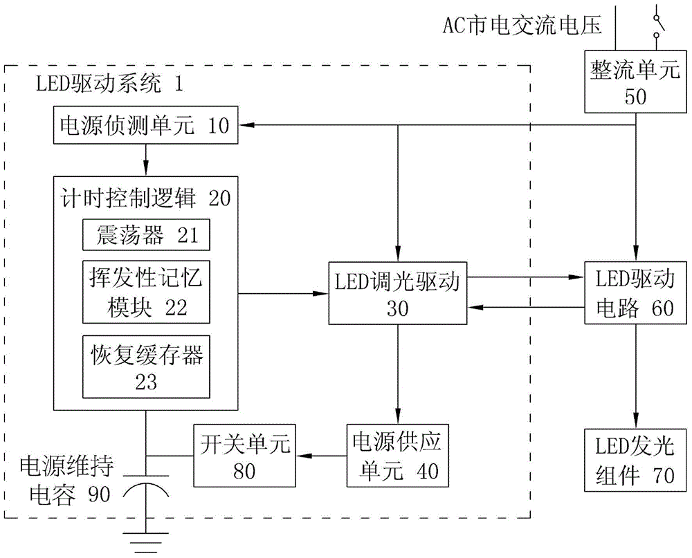
[0034] see figure 1, which is a schematic diagram of an embodiment of an LED drive system for precise timing control and dimming according to the present invention. As shown in the figure, the LED driving system 1 with precise timing control and dimming of the present invention ...


PUM


Abstract

A light emitting diode driving system with precise timing switched dimming control used for driving light emitting diode elements is provided, which comprises a power detection unit, a timer control logic, a light emitting diode dimming driver, and a power supply unit being able to overcome different conditions of power source, switch leakage, and system elements to design the timer dimming with steady and precise working status, and solve problems of each of the independent systems which are not synchronized due to imprecisely timed under power-off condition, while providing various dimming mode for users, and a dimming method using aforementioned LED driving system.

Description

technical field [0001] The present invention relates to a light emitting diode drive system, in particular to a light emitting diode (Light emitting diode, LED) drive system for precise timing control switch dimming and a light emitting diode (Light emitting diode, LED) drive for precise timing control switch dimming The dimming method of the system. Background technique [0002] Due to the increasingly serious energy crisis in the world, light-emitting diodes (LEDs) have been highly valued as a high-efficiency light source. White LEDs have been widely used not only in the backlight sources of mobile phones, PDAs, and LCD TVs in consumer electronics products, but also in public transportation. Signal signs, industrial communication lighting systems, automotive lamps and general industrial and civil lighting with huge consumption will also be widely used. [0003] Moreover, for LED light sources, dimming is easier to realize than other fluorescent lamps, energy-saving lamps,...

Claims


Application Information

Patent Timeline
Patent Type & Authority Applications(China)
IPC IPC(8): H05B37/02H05B44/00
CPCH05B37/0281H05B33/0815H05B33/0851H05B45/10H05B47/16Y02B20/30
Inventor 杨金新
Owner 杨金新
Why Eureka
Try Eureka