Automatic control bending machine

A bending machine and machine body technology, applied in the field of automatic control bending machine, can solve the problems of low work efficiency, large size difference, and fixing of main steel bars, etc.

Inactive Publication Date: 2015-11-11
CHENGDU MATSUKAWA METAL MATERIALS
View PDF5 Cites 0 Cited by
  • Summary
  • Abstract
  • Description
  • Claims
  • Application Information

AI Technical Summary

Problems solved by technology

[0003] When the traditional bending machine bends the stirrup, it is manually bent multiple times, which not only has low w...

Method used


Image

  • Automatic control bending machine
  • Automatic control bending machine
  • Automatic control bending machine

Examples


Embodiment Construction

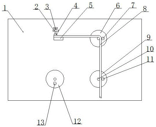
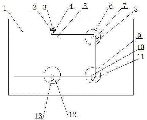
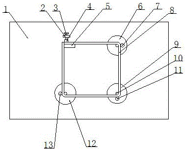
[0012] The present invention will be described in further detail below through specific implementation examples and in conjunction with the accompanying drawings.

[0013] Figure 1-3 The automatic control bending machine provided by the present invention is shown, including body 1, fixed plate 2, threaded rod 3, pressing block 4, baffle plate 5, first working disc 6, first bending pin 7, steel bar 8 , The second working disc 9, the center pin 10, the second bending pin 11, the third working disc 12 and the third bending pin 13. Three bending devices are arranged on the working surface of the body 1, and the three bending devices are distributed in a right-angled isosceles triangle; the bending device includes a working disk, and the center of the working disk is provided with a central pin shaft, and the central pin shaft is provided with a force bearing. sensor; the working disk is provided with a slot, the bottom of the slot is provided with an induction sensor, and a bend...


PUM


Abstract

The invention discloses an automatic control bending machine. The automatic control bending machine comprises a machine body. Three bending devices are arranged on the working face of the machine body and are distributed in a right angled isosceles triangle shape. Each bending device comprises a working disk, wherein a center hinge pin is arranged in the center of the working disk and provided with a force sensor; a slotted hole is formed in the working disk; an inductive sensor is arranged at the bottom of the slotted hole; a bending hinge pin is installed in the slotted hole; the lower end of the working disk is connected with a motor. An electric cabinet is arranged inside the machine body and is connected with the three motors. A baffle is arranged on the working face of the machine body; a fixing plate is arranged on one side of the baffle; a threaded through hole is formed in the fixing plate and is internally provided with a threaded rod; one end of the threaded rod is connected with a press block; the other end of the threaded rod is provided with a handle. The automatic control bending machine can reduce the cost and improve the work efficiency.

Description

technical field [0001] The invention relates to the technical field of mechanical equipment, in particular to an automatic control bending machine. Background technique [0002] With the gradual development of my country's economic construction, large-scale construction projects are being carried out all over the country to build various residential buildings, office buildings, road works and other projects under construction. A large number of steel bars are bent. [0003] When the traditional bending machine bends the stirrup, it manually bends the stirrup multiple times, which not only has low work efficiency and a large amount of labor, but also often has a large size difference and cannot reliably fix the main steel bar. Contents of the invention [0004] The object of the present invention is to provide an automatic control bending machine to solve the deficiencies of the prior art. [0005] In order to achieve the purpose of the present invention, the technical sol...

Claims


Application Information

Patent Timeline
IPC IPC(8): B21F1/00
Inventor 周建川
Owner CHENGDU MATSUKAWA METAL MATERIALS
Why Eureka
Try Eureka