Free state simulating clamping method for bowl-shaped thin-wall ring-shaped part

A ring-shaped part and thin-walled technology, which is applied in the field of imitating free state clamping of bowl-shaped thin-walled ring parts, can solve problems such as clamping deformation and positioning, achieve the effect of eliminating installation tightening deformation and improving processing accuracy

Active Publication Date: 2015-11-11
AECC AVIATION POWER CO LTD
View PDF7 Cites 12 Cited by
  • Summary
  • Abstract
  • Description
  • Claims
  • Application Information

AI Technical Summary

Benefits of technology

This technology allows for more accurate machining by converting different points from one surface onto another without causing damage or distortion during manufacturing processes. It also improves upon how well materials have been shaped beforehand when they come off the machine tool.

Problems solved by technology

This technical problem addressed by this patents relates to finding ways to improve the planarity or quality control required for complex shapes such as cup-shapes made from materials containing strong bearings. Existing techniques involve increasing pressure while maintaining precise alignment, but they may also lead to distortion issues if these processes happen simultaneously without sufficient space around them.

Method used


Image

  • Free state simulating clamping method for bowl-shaped thin-wall ring-shaped part
  • Free state simulating clamping method for bowl-shaped thin-wall ring-shaped part
  • Free state simulating clamping method for bowl-shaped thin-wall ring-shaped part

Examples


Embodiment Construction

[0021] Describe the present invention below in conjunction with specific embodiment:

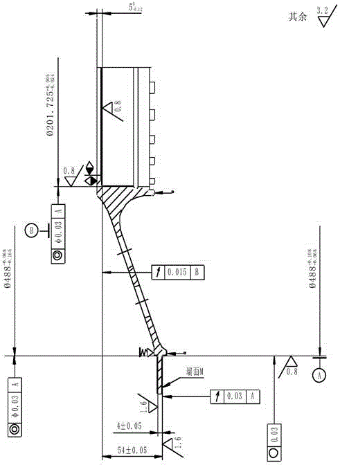
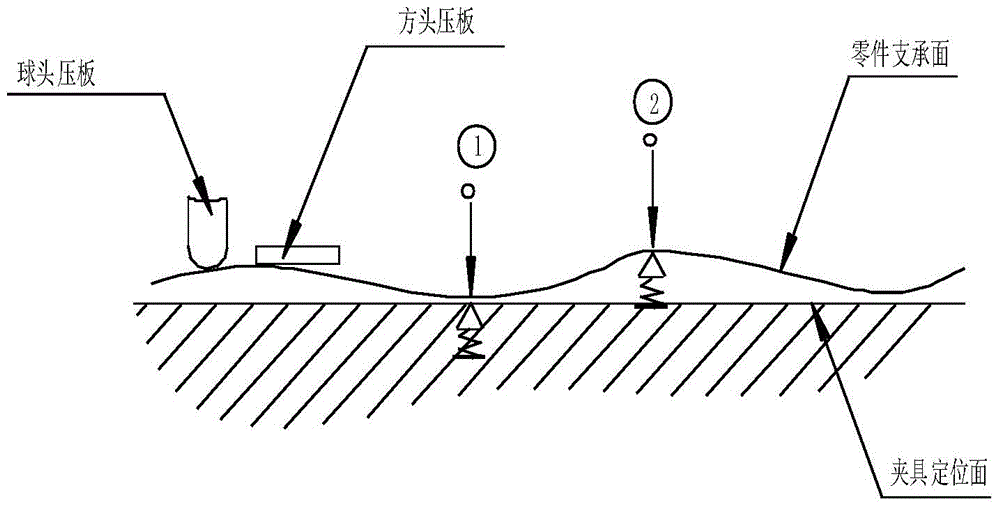
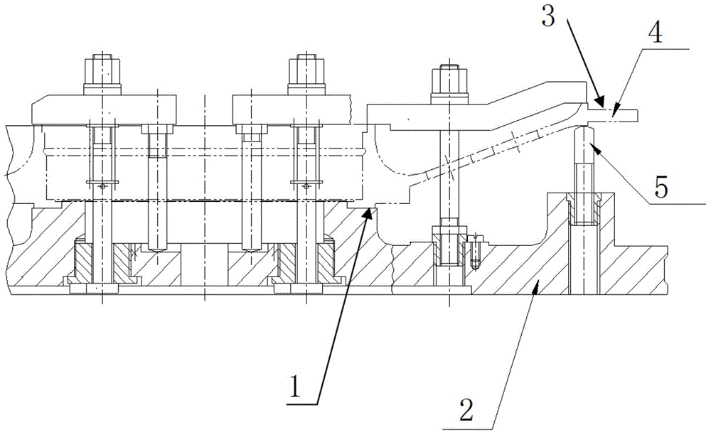
[0022] Such as figure 1 As shown, the bowl-shaped part has a long and thin bowl wall, the inner circle and the adjacent end surface, the outer circle and the adjacent end surface, all have high dimensional accuracy requirements, and at the same time, there is a high degree of precision between the inner shape and the outer shape. The position degree relationship is required, and it is required to be detected in a free state. Due to the high dimensional accuracy of the parts and the poor repeatability of the secondary clamping of thin-walled parts, it is determined that the inner shape of the part must be clamped once and processed at the same time, and the parts must not be deformed during clamping and processing. However, it needs to be pressed during the processing of parts, and there will be deformation when there is a pressing force, especially for thin-walled parts with relatively weak...


PUM


Abstract

The invention provides a free state simulating clamping method for a bowl-shaped thin-wall ring-shaped part. According to the free state simulating clamping method, singular face-to-face relations between a located face of the part and a locating face of a clamp and between a compressed surface of the part and the surface of a compressing piece are converted into multiple independent point-to-point relations through a stud with a spherical top end and a press plate with an cambered compressing face, so that force borne by the part is only the pressure stress borne at force bearing points in material of the part, and the overall structural deformation of the part is not influenced at all; and the strength and the hardness of the material of the part are far larger than those of the material of a compressing mechanism, and therefore point-contact compressing force will not cause material deformation of the part.

Description


Claims


Application Information

Patent Timeline
Owner AECC AVIATION POWER CO LTD
Why Eureka
Try Eureka