
Device for removing burrs on cut portion of window frame

A cutting part and deburring technology, which is applied in the field of deburring devices for the cutting part of window frames, can solve the problems of easy injury to installers, low burr removal efficiency, and damage to the health of operators.

Inactive Publication Date: 2015-11-11
ANHUI KATA DOOR & WINDOW
View PDF8 Cites 0 Cited by
  • Summary
  • Abstract
  • Description
  • Claims
  • Application Information

AI Technical Summary

Problems solved by technology

[0004] The profile will leave burrs at the end after cutting, which is easy to hurt the installer during installation, so deburring must be performed after cutting
[0005] Hand-held deburring devices are the most commonly used deburring tools. However, this working method is not only inefficient in removing burrs, but also in the process of deburring, the splashed metal particles are easy to hurt people, and the splashed plastic powder is easy to be manipulated at close range. inhaled into the lungs of the operator, harming the health of the operator

Method used


Image

  • Device for removing burrs on cut portion of window frame
  • Device for removing burrs on cut portion of window frame

Examples


Embodiment Construction

[0016] In order to make the technical means and creative features realized by the present invention easy to understand, the present invention will be further elaborated below.

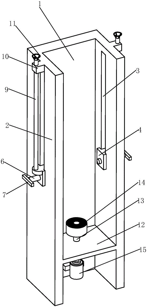
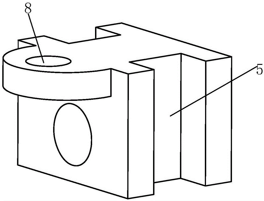
[0017] Such as Figure 1 to Figure 2 As shown, a window frame cutting part deburring device includes a riser 1, the front and rear sides of the riser 1 are provided with baffles 2 perpendicular to the riser 1, each of the baffles 2 is provided with a The strip-shaped hole 3 opened in the vertical direction is provided with a slider 4 in the strip-shaped hole 3, and the left and right sides of the slider 4 are provided with grooves 5 that cooperate with the strip-shaped hole 3. There are also threaded rods 6 in the longitudinal direction of the sliders 4 through threaded fit, and the inner ends of the threaded rods 6 pass through the sliders 4 and extend into the risers 1, and are equipped with pads made of rubber. The outer end of threaded rod 6 is all equipped with turning handle 7, and the upper end...


PUM


Abstract

The invention relates to a device for removing burrs on a cut portion of a window frame. The device comprises a vertical plate. Baffles perpendicular to the vertical plates are arranged on the front side and the rear side of the vertical plate respectively. A strip-shaped hole is formed in each baffle in the vertical direction. Sliding blocks are clamped in the strip-shaped holes respectively. Grooves are formed in the left side face and the right side face of each sliding block respectively. Threaded rods penetrate through the sliding blocks respectively. The inner ends of the threaded rods penetrate through the sliding blocks to extent into the vertical plate. Connecting holes are formed in the upper ends of the sliding blocks respectively. A lead screw penetrates through each connecting hole. The lead screws are parallel to the corresponding strip-shaped holes. The front side and the rear side of the upper end of the vertical plate are each provided with a sleeve block. The upper ends of the lead screws penetrate through the corresponding sleeve blocks respectively in a threaded fit mode. Flange rotary discs are mounted at the upper ends of the lead screws respectively. According to the device for removing the burrs on the cut portion of the window frame, the window frame is placed in the vertical plate, cushion blocks on the corresponding sides are pushed inwards by rotating rotary handles on the two sides simultaneously, and thus the window frame can be pressed between the baffles. The front-back position of the window frame in the vertical plate can also be adjusted by adjusting the rotary handles on the two sides.

Description

technical field [0001] The invention relates to the technical field of door and window processing equipment, in particular to a deburring device for a window frame cutting part. Background technique [0002] Glass is widely used in doors and windows, and with the development of technology and the improvement of people's living standards, the forms of doors and windows are also showing a variety of diversified development trends. [0003] Doors and windows mainly include glass and frames. The frames of doors and windows are mostly made of metal or plastic profiles. The metal or plastic profiles are cut and shaped according to the size of the glass, and then installed on the edge of the glass. [0004] The profile will leave burrs at the end after cutting, which is easy to hurt the installer during installation, so deburring must be performed after cutting. [0005] Hand-held deburring devices are the most commonly used deburring tools. However, this working method is not onl...

Claims


Application Information

Patent Timeline
IPC IPC(8): B24B9/04B24B9/20
CPCB24B9/04B24B9/20
Inventor 李庭凤
Owner ANHUI KATA DOOR & WINDOW
Learn More