
Full-automatic aggregation machine

A granulator and fully automatic technology, which is applied in the field of plastic granulation processing, can solve the problems of a large amount of leftover materials, high energy consumption of equipment, and low production efficiency, so as to achieve high production efficiency, good effect and avoid waste.

Active Publication Date: 2015-11-11
GUANGZHOU 3E MACHINERY
View PDF2 Cites 3 Cited by
  • Summary
  • Abstract
  • Description
  • Claims
  • Application Information

AI Technical Summary

Problems solved by technology

[0002] In the plastic granulation production line, the current process for plastic or chemical fiber materials to achieve the granulation effect is to extrude them into agglomerates through special machinery, and then use a granulator for granulation treatment. Two sets of equipment are required in the production process. Therefore, the production cost is high, the equipment consumes a lot of energy, and the production efficiency is low; and when the extruder is working, it needs to be preheated before the material can be extruded normally; Produce a large amount of leftovers, resulting in waste of materials

Method used


Image

  • Full-automatic aggregation machine
  • Full-automatic aggregation machine
  • Full-automatic aggregation machine

Examples


Embodiment Construction

[0025] Embodiments of the present invention are described in detail below in conjunction with accompanying drawings:

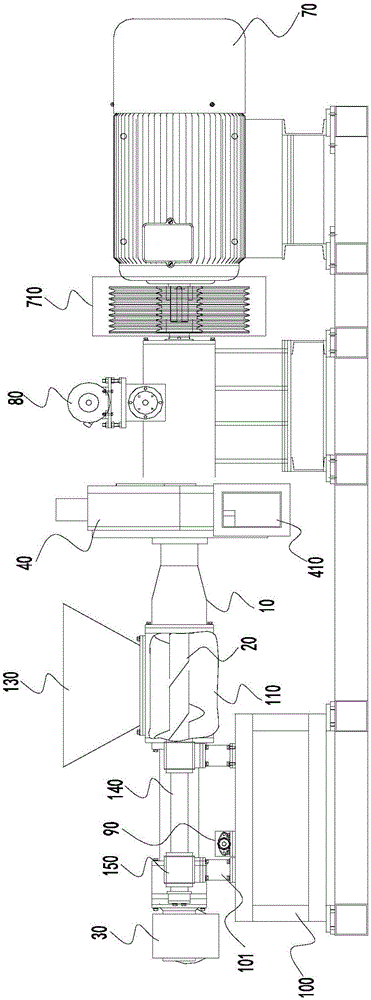
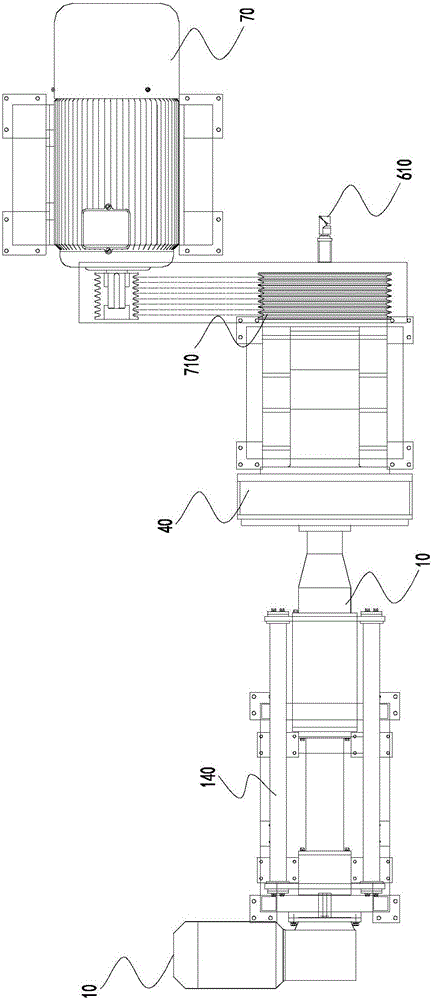
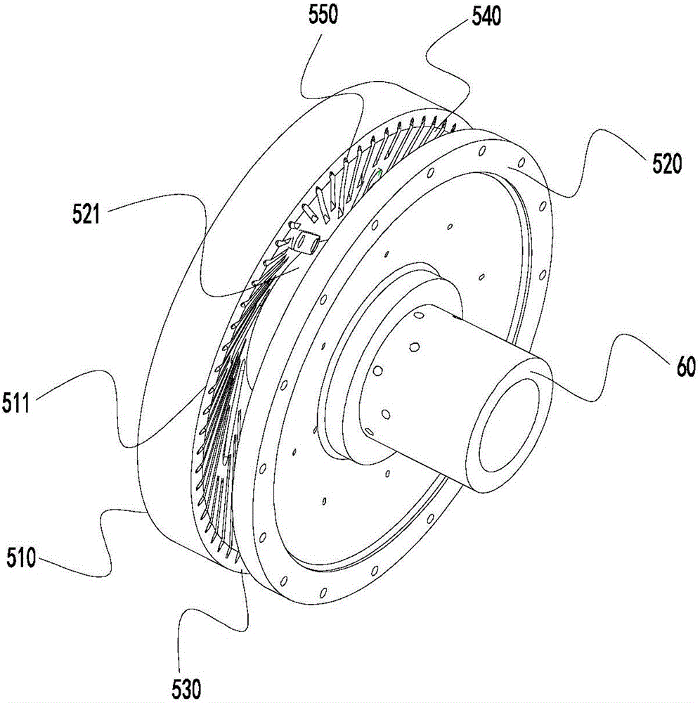
[0026] Such as Figure 1 to Figure 3 As shown, a fully automatic agglomeration machine includes a feed cylinder 10 provided with a feed chamber 110, a feed screw 20 located in the feed chamber 110, a first drive device 30 for driving the feed screw 20 to rotate, and a grinding disc shell 410, the fixed cutterhead 510 and the movable cutterhead 520 located in the grinding disc shell 410, the main shaft 60 sleeved with the movable cutter head 520, the second drive device 70 for driving the main shaft 60 to rotate, and the third drive device for driving the main shaft 60 to move along the central axis. Drive device 80, controller (not identified in the accompanying drawings), fixed cutter head 510 and movable cutter head 520 are arranged oppositely, and form abrasive material chamber 530 between movable cutter head 520, and the bottom of grinding disc shell 410 i...


PUM


Abstract

The invention relates to a full-automatic aggregation machine. The full-automatic aggregation machine comprises a feeding barrel with a feeding cavity, a feeding spiral part located in the feeding cavity, a first drive device driving the feeding spiral part to rotate, a fixed cutter head, a movable cutter head opposite to the fixed cutter head, a main shaft sleeved with the movable cutter head in a connected manner, a second drive device driving the main shaft to rotate, a third drive device driving the main shaft to move along the center axis, and a controller. A grinding cavity is formed between the fixed cutter head and the movable cutter head. The grinding cavity is internally provided with a temperature sensor electrically connected with the controller. The controller is electrically connected with the second drive device and the third drive device. Materials are fed into the grinding cavity through rotation of the feeding spiral part, the movable cutter head rotates to enable the materials entering the grinding cavity to rub, and the materials are thrown out of the edge of the cutter heads through the centrifugal action so that particle cutting can be achieved, and the purposes of material extruding and particle cutting are achieved at a time. A gap between the movable cutter head and the fixed cutter head can be adjusted through the third drive device, the control over balanced feeding and aggregating effects is achieved, and the quality of products is guaranteed.

Description

technical field [0001] The invention relates to the technical field of plastic granulation processing, in particular to an automatic agglomerating machine. Background technique [0002] In the plastic granulation production line, the current process for plastic or chemical fiber materials to achieve the effect of granulation is to extrude them into agglomerates through special machinery, and then use a granulator for granulation treatment. Two sets of equipment are required in the production process. Therefore, the production cost is high, the equipment consumes a lot of energy, and the production efficiency is low; and when the extruder is working, it needs to be preheated before the material can be extruded normally; A large amount of leftover materials are produced, resulting in waste of materials. Contents of the invention [0003] The purpose of the present invention is to provide a fully automatic agglomerator, which can automatically and evenly complete the extrusi...

Claims


Application Information

Patent Timeline
Patent Type & Authority Applications(China)
IPC IPC(8): B29B9/06B02C18/06B02C18/18B02C18/22B02C18/16
CPCB29B9/065
Inventor 张雷
Owner GUANGZHOU 3E MACHINERY
Learn More