Photovoltaic curtain wall and double-source heat pump integrated system suitable for cold area

A dual-source heat pump, cold area technology, applied in heat pumps, refrigerators, heating devices, etc., can solve problems such as difficulty in promotion and use in cold areas, decreased operating efficiency of soil source heat pumps, and lack of overall integrated solution design, resulting in increased costs. Less investment, short payback period, and the effect of improving power generation efficiency

Inactive Publication Date: 2015-11-11
SHENYANG JIANZHU UNIVERSITY
View PDF7 Cites 4 Cited by
  • Summary
  • Abstract
  • Description
  • Claims
  • Application Information

AI Technical Summary

Problems solved by technology

[0007] However, the existing heat pumps and systems have not been considered in combination with actual conditions, and lack of overall integrated design for specific situations. For example: air source heat pumps can obtain low-grade heat from the surrounding air to produce domestic hot water, air source The cost of heat pump is low, but it is also limited by the outdoor air temperature, so it is difficult to promote and use in cold areas, and the combination of building-integrated PVT system is expected to overcome this problem; The heat emitted downward to the soil is greater than the heat absorbed from the soil under winter heating conditions. Therefore, as the heat pump system operates year by year, heat accumulation will occur in the underground soil, and the soil temperature will gradually increase, resulting in a decrease in the operating efficiency of the soil source heat pump.

Method used


Image

  • Photovoltaic curtain wall and double-source heat pump integrated system suitable for cold area
  • Photovoltaic curtain wall and double-source heat pump integrated system suitable for cold area
  • Photovoltaic curtain wall and double-source heat pump integrated system suitable for cold area

Examples


Embodiment Construction

[0021] In order to make the technical means, creative features, goals and effects achieved by the present invention easy to understand, the technical solutions in the embodiments of the present invention will be clearly and completely described below in conjunction with the accompanying drawings in the embodiments of the present invention.

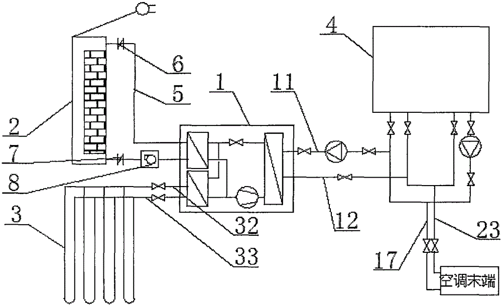
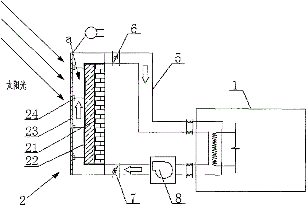
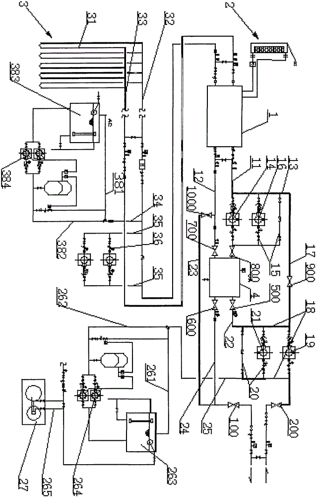
[0022] see Figure 1-3 , this specific embodiment is realized by adopting the following technical scheme, which includes photovoltaic curtain wall 2, ground source heat assembly 3, air source-ground source dual source heat pump unit 1, phase change heat storage tank 4 and corresponding air-conditioning terminal, so The airflow output end of the photovoltaic curtain wall 2 is connected to the air inlet of the air source-ground source dual-source heat pump unit 1 through the pipeline 5 through the first electric control damper 6, and the airflow output end of the photovoltaic curtain wall 2 is connected through the pipeline 5 through the seco...


PUM


Abstract

The invention discloses a photovoltaic curtain wall and double-source heat pump integrated system suitable for a cold area. The system comprises a photovoltaic curtain wall (2), a ground source thermal component (3), an air source-ground source double-source heat pump unit (1), a phase change heat storage water tank (4) and a corresponding air conditioner tail end. The air flow output end of the photovoltaic curtain wall (2) is connected with an air inlet of the air source-ground source double-source heat pump unit (1) through a first electronic control air valve (6) through a pipeline (5). The air flow output end of the photovoltaic curtain wall (2) is connected with an air outlet (9) of the air source-ground source double-source heat pump unit (1) through a second electronic control air valve (7) and a draught fan (8) through the pipeline (5). By means of the system, double-effect utilization of solar thermoelectricity is achieved, and the power generation efficiency of a silicon cell is improved due to the fact that a PVT device is cooled; peak load shifting of solar energy is achieved; the problem that the solar heating guaranteeing rate is low is effectively solved, and one machine is provided with two sources; and cost increase is small, and the period of investment return is short.

Description

technical field [0001] The invention belongs to the technical field of renewable energy utilization, and in particular relates to the integrated technology of building heating and cooling. Background technique [0002] Energy, environment and sustainable development are the themes of the survival and development of human society in the 21st century, and the development of solar thermal utilization technology has received global attention. Heat pump technology can effectively improve the quality of low-grade heat sources in nature and meet the demand for cold and heat in buildings and technological processes. In recent years, it has developed by leaps and bounds in my country and the world. However, the operation of the heat pump system is affected by many aspects such as low-level heat sources, climate conditions, and user system conditions. In order to make it operate normally and stably, it often needs to combine other energy sources. [0003] The concept of photovoltaic ...

Claims


Application Information

Patent Timeline
Patent Type & Authority Applications(China)
IPC IPC(8): F25B30/06F25B41/04F24J2/34F25B41/20
CPCY02E10/40
Inventor 冯国会张然黄凯良曹炽洪
Owner SHENYANG JIANZHU UNIVERSITY
Why Eureka
Try Eureka