Refrigerating unit and throttle device

A throttling device and throttling hole technology, applied in refrigerators, refrigeration components, refrigeration and liquefaction, etc., can solve the problems such as the refrigeration and cooling process cannot be carried out normally, the large volume of large refrigeration units, and the failure of throttling effect, etc. The effect of machining and joining, reducing solder leaks, and improving reliability

Inactive Publication Date: 2015-11-11
GREE ELECTRIC APPLIANCES INC
View PDF7 Cites 3 Cited by
  • Summary
  • Abstract
  • Description
  • Claims
  • Application Information

AI Technical Summary

Problems solved by technology

[0004] However, due to the large volume of large-scale refrigeration units, the cleanliness of the system cannot be completely free of slag. If these slag enter the orifice with the flow of refrigerant, it is likely to cause blockage of the orifice, resulting in the failure of the throttling effect, making the The refrigeration and cooling process cannot be carried out normally
[0005] At present, there is also a filter screen in front of the pipeline to prevent the entry of slag, but it undoubtedly increases the material. At the same time, because the filter screen is added to the pipeline system, welding leaks are added in the middle

Method used


Image

  • Refrigerating unit and throttle device
  • Refrigerating unit and throttle device
  • Refrigerating unit and throttle device

Examples


Embodiment Construction

[0026] The invention discloses a refrigeration unit and a throttling device thereof. The structure of the refrigeration unit can not only prevent the clogging of the throttling hole, but also simplify the pipeline configuration and reduce the pipeline welding leakage.

[0027] The technical solutions in the embodiments of the present invention will be clearly and completely described below in conjunction with the accompanying drawings in the embodiments of the present invention. Obviously, the described embodiments are only a part of the embodiments of the present invention, rather than all the embodiments. Based on the embodiments of the present invention, all other embodiments obtained by those of ordinary skill in the art without creative work shall fall within the protection scope of the present invention.

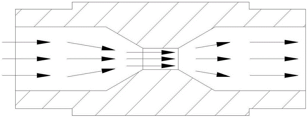
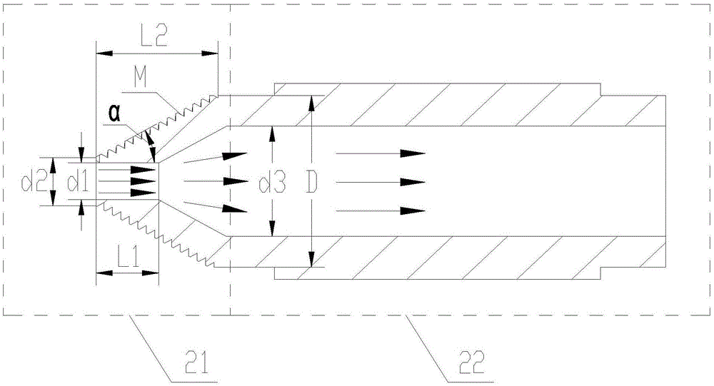
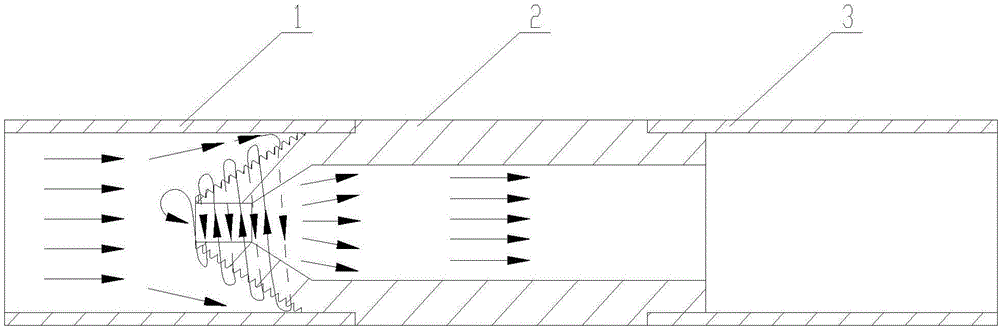
[0028] See figure 2 with image 3 , figure 2 Is a schematic structural diagram of a throttling device provided by an embodiment of the present invention; image 3 It is ...


PUM


Abstract

The invention discloses a throttle device possessing refrigerating throttling effect and an anti-blocking function. The throttle device comprises a front end throttling section and a back end pipeline connection section, wherein the front end throttling section has a throttling and anti-blocking function and is equipped with a throttling hole; outside the throttling hole is provided an inclined wall surface and thread grooves formed on the inclined wall surface; and the back end pipeline connection section has two sections of steps for pipeline connection. Blocking slag can be flushed by spiral impact of fluid in the pipeline, so a self anti-blocking function can be achieved; and the throttle device is simply structured with safety and reliability. The invention further discloses a refrigeration unit having the above throttle device.

Description

Technical field [0001] The invention relates to the technical field of refrigeration equipment, in particular to a refrigeration unit and a throttling device thereof. Background technique [0002] In the refrigeration unit, the throttling device is an indispensable mechanism. At present, the commonly used throttling devices include capillary tubes, throttling orifices, electronic expansion valves, thermal expansion valves, etc. Among them, the throttling orifices are widely used because they have no mechanical moving parts and simple structure. [0003] However, in the process of use, if the device with a small flow rate, the orifice is very small, especially in the large-scale refrigeration unit, the motor cooling, lubricating oil cooling and other devices require very little cooling capacity, so the flow rate that needs to be throttled is also Very small, the natural orifice is also very small, its structure can refer to figure 1 Shown. [0004] However, due to the large volume o...

Claims


Application Information

Patent Timeline
Patent Type & Authority Applications(China)
IPC IPC(8): F25B41/06F25B41/31
CPCF25B41/30
Inventor 钟瑞兴张治平刘华李宏波蒋楠陈玉辉刘建飞谢蓉蒋彩云
Owner GREE ELECTRIC APPLIANCES INC
Why Eureka
Try Eureka