

Sheet conveying apparatus and image forming apparatus
A technology of a conveying device and an imaging device, which is applied in the directions of transportation and packaging, thin material processing, instruments, etc., can solve the problems of wrinkling at the edge of the sheet, and achieve the effect of improving wrinkling.
- Summary
- Abstract
- Description
- Claims
- Application Information
AI Technical Summary
Problems solved by technology
Method used
Image

Examples
no. 1 example
[0038] refer to Figure 1 to Figure 14 , an image forming apparatus provided with the sheet conveying apparatus according to the first embodiment will be described. In the following description, the image forming device will be described first, and then the sheet conveying device will be described. Although the description will be made in the first embodiment in which the sheet conveying device is connected to the image forming device outside the image forming device, the present invention can also be applied to an image forming device having a sheet conveying device integrally contained in the image forming device.
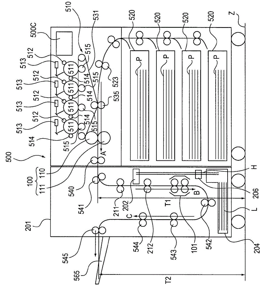
[0039] First, refer to figure 1 , the sheet conveying device and the image forming device detachably connected to the image forming device will be described. figure 1 is a cross-sectional view schematically showing a color electrophotographic printer 500 as an example of an image forming device, a stretch conveying device as an example of a sheet conveying devi...
no. 2 example
[0106] refer to Figure 15 to Figure 20 , the configuration of the load torque generating section 131 surrounding the sheet wrinkle correcting device 301 , the sheet humidifying device 302 , and the sheet stretching conveyance device 101 will be described.
[0107] Since the configuration and operation other than those surrounding the sheet humidifying device 302 and the load torque generating part 131 of the sheet tension conveying device 101 are the same as those in the first embodiment, description thereof is omitted. In addition, the humidifying liquid L and the sheet P are the same as those in the first embodiment, and thus are denoted by the same reference numerals.
[0108] Figure 15 is a block diagram showing the control relationship in the entire image forming apparatus 500 and the sheet wrinkle correcting apparatus 301 .
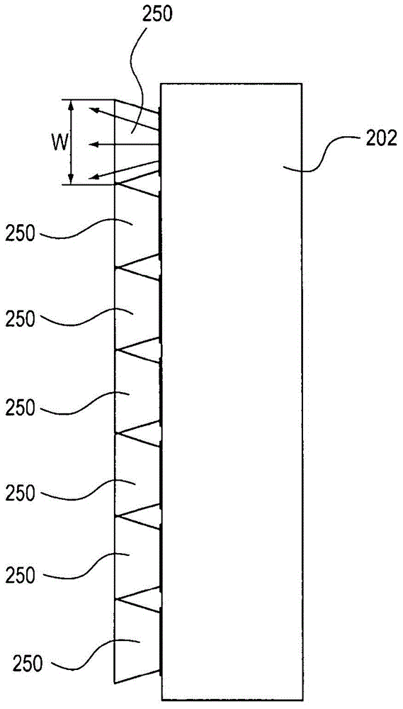
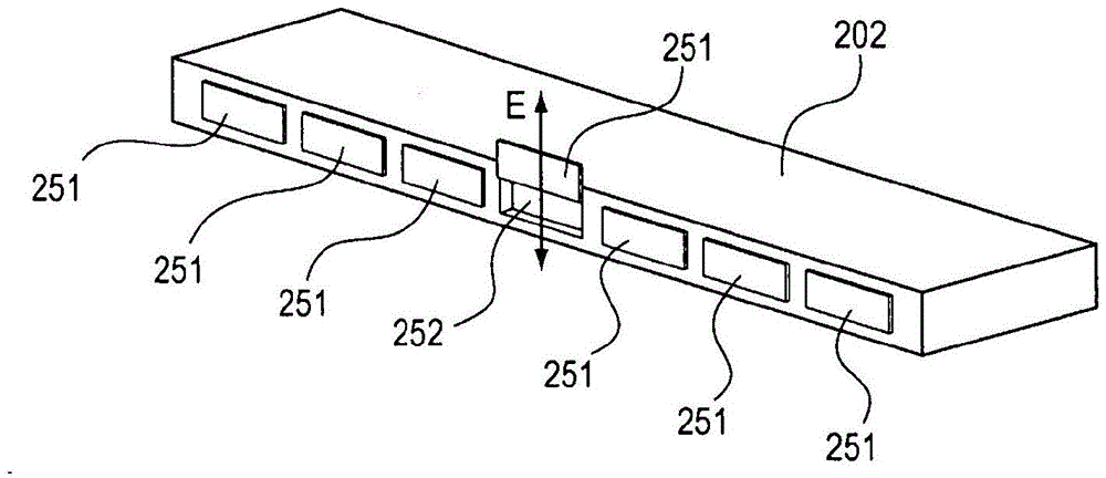
[0109] In the sheet wrinkle correcting apparatus 301 according to the present embodiment, the spray sheet humidifying apparatus 202 according t...
no. 3 example
[0138] refer to Figure 21 , the third embodiment will be described. In the present embodiment, the same configuration is adopted except for the point that only the stretch conveyance device is changed in the sheet processing apparatus according to the first embodiment. Accordingly, descriptions other than the stretching transfer device will be omitted.
[0139] A point different from the first embodiment is that the pair of rotating members on the downstream side in the conveying direction of the sheet P is constituted by a pair of belts. Such as Figure 21 As shown, the configuration is such that the sheet P wraps around the second drive belt 147 and is stretched to effect elongation of the sheet.
[0140] The belt pair includes a second drive belt 147 and a second pressure belt 148 . The second driving belt 147 includes the second driving endless belt 133 , the second driving roller 106 , the second driving side endless belt roller 135 and the second driving side pressu...
PUM
 Abstract
Description
Claims
Application Information