Synchronization method for asynchronous device

A technology of asynchronous devices and active devices, applied in the direction of synchronous devices, digital transmission systems, electrical components, etc., can solve the problems of reduced flexibility, low feasibility, and poor versatility, and achieve high flexibility, high feasibility, and improved system The effect of stability

Active Publication Date: 2015-11-11
NR ELECTRIC CO LTD +1
View PDF5 Cites 4 Cited by
  • Summary
  • Abstract
  • Description
  • Claims
  • Application Information

AI Technical Summary

Problems solved by technology

At present, the commonly used synchronization method is to maintain synchronization between different subsystems through the external interrupt mode. This synchronization method requires the execution cycle of each subsystem to be consistent, and the fl...

Method used


Image

  • Synchronization method for asynchronous device
  • Synchronization method for asynchronous device
  • Synchronization method for asynchronous device

Examples


Embodiment 1

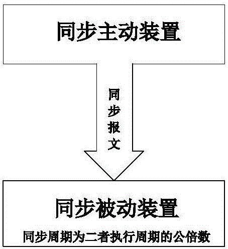
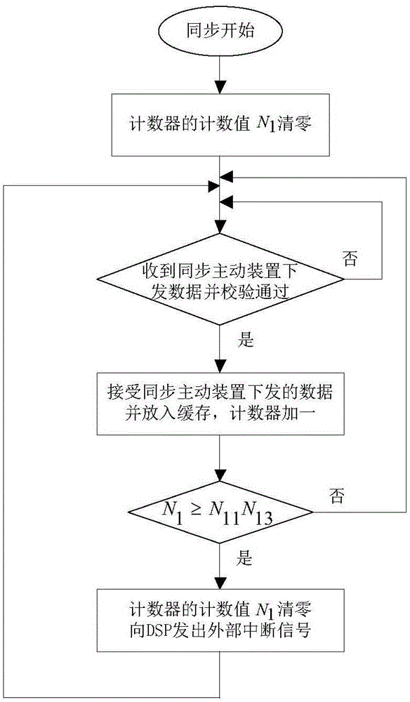
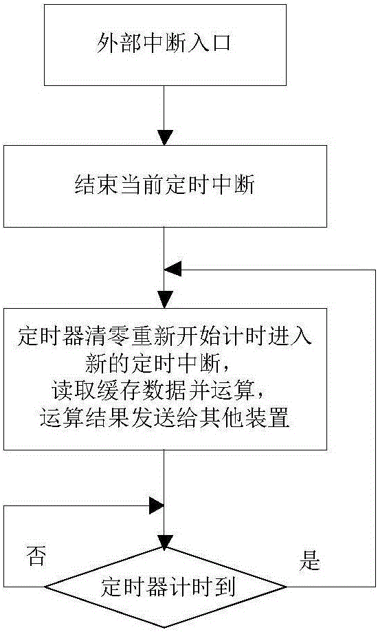
[0034] Such as figure 1 As shown, the synchronization method of the asynchronous device includes a synchronous active device, a synchronous passive device and a communication channel between the two, and the nominal execution cycle of the synchronous active device is T 11 , the nominal execution period of the synchronous passive device is T 12 . Get T 11 with T 12 The least common multiple of is equal to T 13 , namely T 13 =N 11 T 11 =N 12 T 12 , the synchronous master executes the cycle T according to the nominal 11 Calculate and send communication messages to the synchronous passive device, and the synchronous passive device follows the nominal execution cycle T 12 Execute timing interrupt, according to the synchronous cycle T 14 Synchronize to the active synchronization device, the synchronization period T 14 is T 13 N 13 times, T 14 =N 13 T 13 , the synchronization steps are as figure 2 As shown, the specific steps are as follows:

[0035] (1) The inter...

Embodiment 2

[0045] Such as figure 1 As shown, the synchronization method of the asynchronous device includes a synchronous active device, a synchronous passive device and a communication channel between them. The nominal execution period of the synchronous master is T 21 , the nominal execution period of the synchronous passive device is T 22 . Get T 21 with T 22 The least common multiple of is equal to T 23 , namely T 23 =N 21 T 21 =N 22 T 22 , the synchronous master executes the cycle T according to the nominal 21 Calculate and send communication messages to the synchronous passive device, and the synchronous passive device executes the cycle according to the compensation Execute timing interrupt, according to the synchronous cycle T 24 Synchronize to the active synchronization device, the synchronization period T 24 is T 23 N 23 times, T 24 =N 23 T 23 , execution cycle after compensation The solution method is as Figure 4 As shown, the specific steps are as follo...


PUM


Abstract

The invention discloses a synchronization method for an asynchronous device. The method comprises a first step that an interface unit of a synchronous passive device verifies the data received from a synchronous active device, the data passing through the verification is cached, and a count value N1 of a counter is added by 1; a second step that the count value N1 is compared with N11N13, if N1 is greater than or equal to N11N13, a step 3 is performed, if not, the step 1 is performed; a third step that the count value N1 is reset, and an external interruption signal is sent to an arithmetic unit of the synchronous passive device; a fourth step that the arithmetic unit of the synchronous passive device receives the external interruption signal, and then finishes current timer interruption; a fifth step that a timer is reset and restarts timing, when in a new timer interruption, cache data is read and calculated, and an operation result is sent to other devices; and a sixth step that if T12 of a timing time of the timer is not achieved, it needs to keep waiting, or else, the step 5 is performed. No extra synchronous device is added; the synchronization performance is excellent, the power of a converter is prevented from periodic oscillation, and the system stability is improved; and the method has high flexibility and high engineering application feasibility.

Description

technical field [0001] The invention belongs to the technical field of power electronics, and in particular relates to a synchronization method for an asynchronous device. Background technique [0002] With the development of power electronics technology, converters based on fully controlled semiconductor devices are widely used in the fields of new energy power generation and flexible AC-DC transmission. This type of converter has fast dynamic response and flexible control, but it also puts forward higher requirements for control performance, so designing a high-speed and reliable control system is very important for control performance. [0003] In the field of low-power applications, the sampling, control and driving links in the control system are usually completed by the same processor, and all links are naturally synchronized and have good real-time performance. However, with the wide application of power electronics technology in the field of high-power applications,...

Claims


Application Information

Patent Timeline
IPC IPC(8): H04L7/00
Inventor 丁久东李钢鲁江胡兆庆董云龙卢宇汪楠楠王柯
Owner NR ELECTRIC CO LTD
Why Eureka
Try Eureka