
Microscope having a transmitted-light lighting device for critical lighting

A microscope and transmitted light technology, applied in the field of microscopy, can solve the problems of costing money and low light source requirements, and achieve the effect of high illumination intensity

Active Publication Date: 2015-11-11
LEICA MICROSYSTEMS (SCHWEIZ) AG
View PDF6 Cites 2 Cited by
  • Summary
  • Abstract
  • Description
  • Claims
  • Application Information

AI Technical Summary

Problems solved by technology

[0008] Therefore, it is very expensive to provide good quality critical illumination, so for more expensive microscopes basically only so-called Koehler illumination is used, which has low light source requirements

Method used


Image

  • Microscope having a transmitted-light lighting device for critical lighting
  • Microscope having a transmitted-light lighting device for critical lighting
  • Microscope having a transmitted-light lighting device for critical lighting

Examples


Embodiment Construction

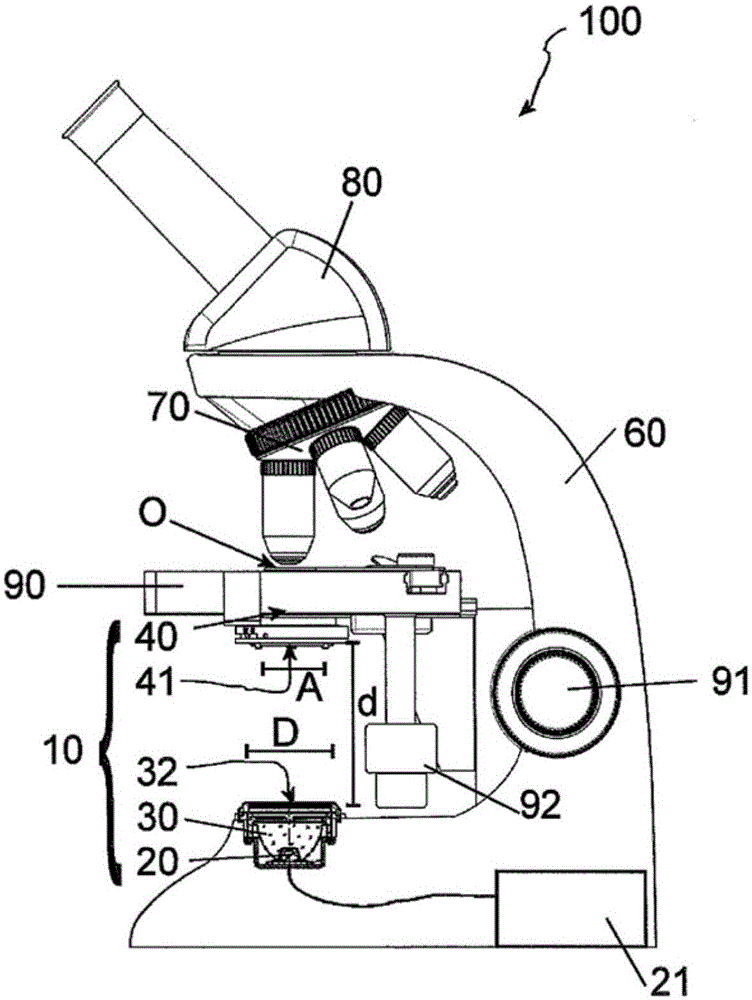
[0041] figure 1 A schematic side view of a preferred embodiment of the microscope 100 according to the invention is shown in FIG. The microscope 100 is used to observe the object O placed on the microscope stage 90 . The microscope has a mount 60 for supporting various microscope components, in particular a transmitted light illumination unit 10 , an objective swivel 70 with various objectives 71 and a tube 80 with eyepieces.

[0042] The microscope stage can be moved in z or x / y directions by knobs 91 and 92 in a known manner.

[0043] The transmitted light illumination device 10 has a light source 20 designed as an LED arrangement. The energy supplier 21 is used to supply the LED device. Above the LED device 20 is arranged a light-directing unit 30, which on its side facing the object O to be illuminated has a larger output surface 32, the size of which (here diameter; usually can also be through the geometric center The maximum or minimum extension distance) is D. The...


PUM


Abstract

The invention relates to a microscope (100) having a transmitted-light lighting device (10) for critical lighting of an object (O) to be observed, comprising: a light source (20) having an LED assembly having a light-emitting surface, a light-directing unit (30, 30') having a collimator (35, 35') and a reflecting jacket surface (34, 34'), both for orienting light coupled into the light-directing unit (30, 30'), and having an outcoupling surface (32, 32'), wherein the outcoupling surface (32, 32') has an outcoupling surface dimension (D), wherein the light-emitting surface of the light source (20) is smaller than the outcoupling surface (32, 32') of the light-directing unit (30, 30'), wherein the light-directing unit (30, 30') is arranged in such a way that light emitted by the light source (20) is coupled in and is coupled out from the outcoupling surface (32, 32'), a condensor (40) between the outcoupling surface (32, 32') of the light-directing unit (30, 30') and the object (O) to be observed, wherein the condensor has an aperture (41) having an aperture dimension (A) and is arranged in such a way that the aperture (41) is completely irradiated with the light coupled out from the outcoupling surface (32, 32').

Description

technical field [0001] The invention relates to a microscope with transmitted light illumination for critical illumination. Background technique [0002] Common light sources such as those used in light microscopy (such as incandescent coiled filaments or LED arrays) are inherently very inhomogeneous and therefore often use diffusers (diffusion sheets in most cases), which lead to loss of light in the direction of the sample , and thus the light source must be correspondingly bright. [0003] Simple microscopes often use so-called critical illumination, which can be managed with a small number of optics. Typically at least the collector and field aperture are omitted. The object is located substantially at the sample-side focal point of the light collector, which is illuminated over a large area with substantially parallel light. The aperture stop that is sometimes present is essentially at the focal point on the lamp side of the condenser. Inhomogeneities in the far fie...

Claims


Application Information

Patent Timeline
Patent Type & Authority Applications(China)
IPC IPC(8): G02B3/00G02B5/02G02B21/08
CPCG02B21/086G02B3/0056G02B5/005G02B5/021G02B17/006G02B21/06G02B27/30
Inventor 冈特·格雷伯罗伯特·鲍鲁斯
Owner LEICA MICROSYSTEMS (SCHWEIZ) AG
Learn More