
Spiral rebar connector

A technology of spiral steel bars and connectors, applied in the direction of structural elements, building components, building reinforcements, etc., can solve the problems of inability to fully utilize the mechanical properties of materials, unfavorable seismic performance of prefabricated structures, and uncoordinated concrete deformation, and achieve deformation coordination. , low cost and convenient construction

Inactive Publication Date: 2015-11-18
BEIJING UNIV OF TECH
View PDF5 Cites 0 Cited by
  • Summary
  • Abstract
  • Description
  • Claims
  • Application Information

AI Technical Summary

Problems solved by technology

[0004] The metal grouting sleeve is currently the most widely used fabricated structural connector. A large number of experiments and researches have proved that it has the characteristics of effectively transmitting axial loads; however, many recent academic studies have shown that due to the resistance of the metal sleeve itself The side stiffness is relatively large, and the existence of multiple connectors at the joints makes the connector area rigid, resulting in the incoordination between the deformation of the concrete in the sleeve area and the surrounding concrete, and most of the cracks generated by the deformation are concentrated on the concrete outside the connector area , cannot make full use of the mechanical properties of the material, which is not conducive to the overall seismic performance of the prefabricated structure
[0005] It can be seen that the current connection method of fabricated components still has certain technical defects. Therefore, a connector with good tensile performance and soft lateral stiffness is needed, which can make the steel bar meet the axial load under the earthquake load. The requirements of the load action can also coordinate the deformation of the components in the connection area

Method used


Image

  • Spiral rebar connector
  • Spiral rebar connector
  • Spiral rebar connector

Examples


Embodiment Construction

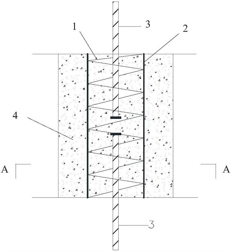
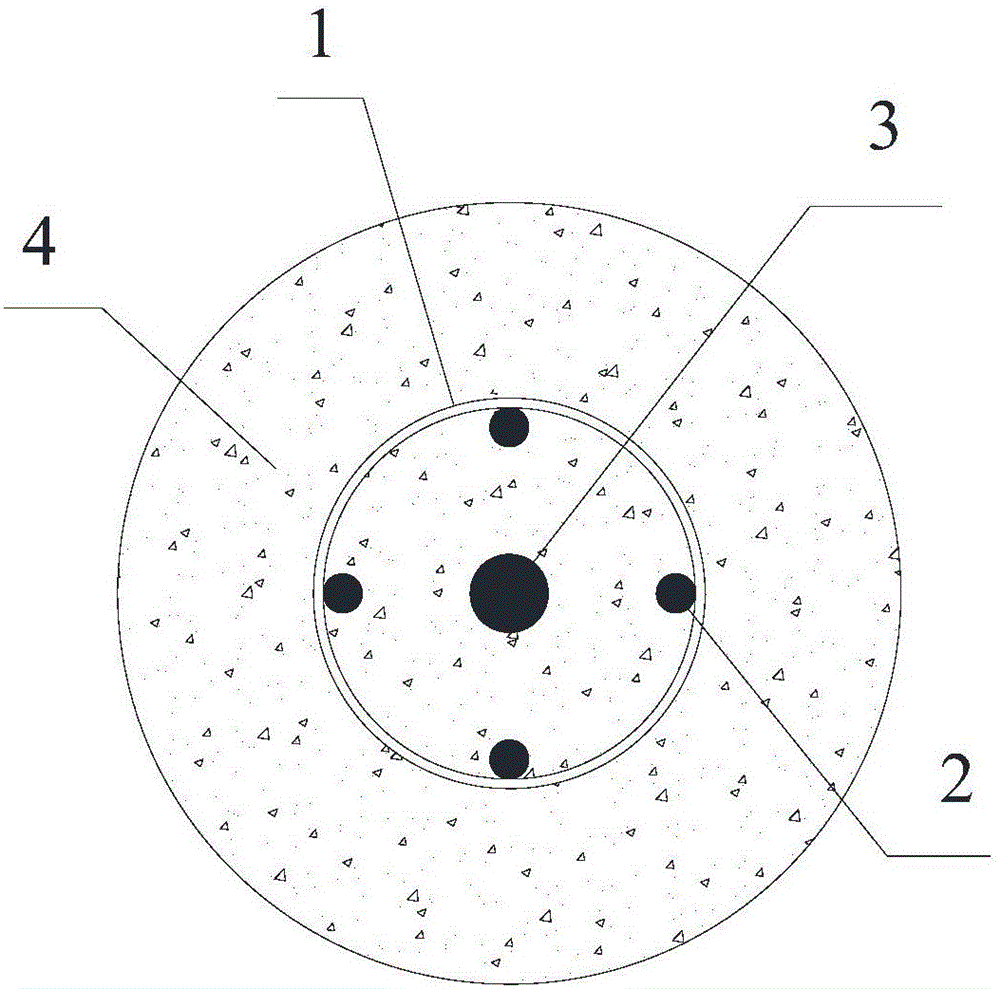
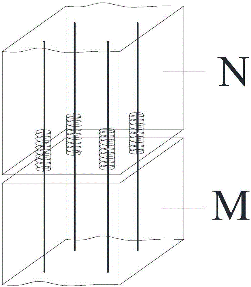
[0014] When the building structure needs to connect steel bars between components, the spiral steel bar connector of the present invention can be used to achieve the mechanical properties not lower than the direct connection of steel bars. The present invention can not only be used in the design and construction of new buildings, but also in the seismic reinforcement of existing buildings, such as Figure 1-Figure 3 As shown, among them, figure 1 It is a structural schematic diagram of a spiral steel bar connector according to the present invention, figure 2 for figure 1 The A-A section diagram, image 3 It is a schematic diagram of the application of the present invention; it specifically includes: 1—spiral steel bar, 2—lapped steel bar, 3—connected steel bar, 4—grouting material, M—lower prefabricated component, N—upper prefabricated component.

[0015] Among them, the spiral steel bar can fix no less than one lapped steel bar, and a larger number of lapped steel bars ca...


PUM


Abstract

The invention discloses a spiral rebar connector, and belongs to the technical field of constructional engineering. The spiral rebar connector is characterized by comprising a spiral rebar and lap-joint rebars, wherein the spiral rebar and the lap-joint rebars are fixed; the number of the lap-joint rebars is not less than 1; to-be-connected rebars are connected through grouting in the spiral rebar; and the lap-joint rebars are fixed on the spiral rebar to guarantee tensile properties of the spiral rebar connector. The spiral rebar has a restraint effect on grouting materials, thereby enhancing the interaction of the rebars and the grouting materials. The spiral rebar connector enables connecting areas to easily deform and coordinate with surrounding materials through small resistant-lateral rigidity and by adopting a mounting method of area grouting. The spiral rebar connector has the advantages of simple process, low cost, reliable performance and the like, is particularly suitable to connect rebars between assembled components, can be widely applied to assembled concrete structures, and has a wide prospect of engineering application.

Description

technical field [0001] The invention relates to a grouting connector used for connecting steel bars between prefabricated concrete components, belonging to the technical field of construction engineering, in particular to a spiral steel bar connector. Background technique: [0002] Prefabricated concrete structure, as a structural form conforming to industrial production mode, has the advantages of fast construction speed, low labor intensity, less noise pollution and wet operation, and easy control of product quality, and has been widely used in countries all over the world. The construction method of prefabricated assembly can effectively save resources and energy, improve the utilization rate of materials in realizing building energy saving and enhancing structural performance, overcome the restrictions of construction site and environmental conditions on site construction, reduce the scale of on-site construction labor force, and ease construction The adverse impact of w...

Claims


Application Information

Patent Timeline
Patent Type & Authority Applications(China)
IPC IPC(8): E04C5/18
Inventor 许成顺江志伟杜修力路德春
Owner BEIJING UNIV OF TECH
Learn More