

Parking space management device
A technology for parking space management and parking spaces, applied in the field of parking space management equipment, to achieve the effects of wide application range, accurate recording and control of charges, and ingenious structural design
- Summary
- Abstract
- Description
- Claims
- Application Information
AI Technical Summary
Problems solved by technology
Method used
Image

Examples
Embodiment 1
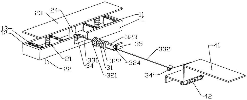
[0044] Embodiment one, such as Figure 1 to Figure 10 shown.
[0045] Including base, pressing plate execution, wire rope transmission mechanism, baffle actuator and other accessories.
[0046] Base 1 can be improved on the basis of existing parking spaces, or a structure can be made separately, and the base has spaces for accommodating springs, baffle plate actuators, pressing plate actuators, and wire rope transmission mechanisms.
[0047] Base 1 is rigid and can be made of steel or concrete.
[0048] The pressing plate actuator includes a pressing plate 23 , a guide post 22 , a first spring 21 , and a wire rope connecting post 24 . A rectangular groove 11 is provided in the base 1, and there are two circular round holes and a square square hole in the groove 11, and the rectangular pressing plate 23 is located in the groove 11, and has a movement in the upper and lower positions. space. A pair of guide pillars 22 are welded and fixed on the lower side of the pressure pl...
Embodiment 2
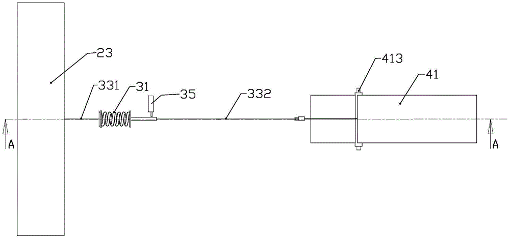
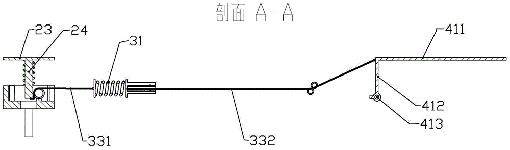
[0064] Embodiment 2, as the second method above, such as Figure 6 to Figure 8 shown
[0065] The difference from Embodiment 1 is that the baffle is Z-shaped, and a horizontal auxiliary board extends outward from the lower part of the vertical board, in which the wire rope fixing point is set on the auxiliary board 414, and the second wire rope 332 is fixed on the auxiliary board on the fixed point of the wire rope.
[0066] The following is a detailed description of how it is used in public parking lots:
[0067] Such as Figure 3 to Figure 5 As shown, requirements: when there is no car in the parking space, the baffle is in a horizontal state. After the car enters the parking space and parks, the baffle will automatically become inclined after a few seconds; after the vehicle is paid, the electric control lock will automatically lock the baffle and automatically become horizontal. state, the vehicle can leave.
[0068] Specifically, the above-mentioned electric control l...
PUM
 Abstract
Description
Claims
Application Information