Drum brake cooled through heat pipes

A technology of drum brakes and heat pipes, which is applied in the field of auto parts, can solve the problems that heat cannot be removed in time and effectively, and achieve the effects of compact structure, strong heat dissipation capacity and convenient installation

Active Publication Date: 2015-11-18
SOUTH CHINA UNIV OF TECH
View PDF8 Cites 17 Cited by
  • Summary
  • Abstract
  • Description
  • Claims
  • Application Information

AI Technical Summary

Problems solved by technology

[0006] Aiming at the problem of heat decay caused by a large amount of heat generated between the friction plate and the inner surface of the brake drum during braking, which cannot be removed in time and effectively

Method used


Image

  • Drum brake cooled through heat pipes
  • Drum brake cooled through heat pipes
  • Drum brake cooled through heat pipes

Examples


Embodiment 1

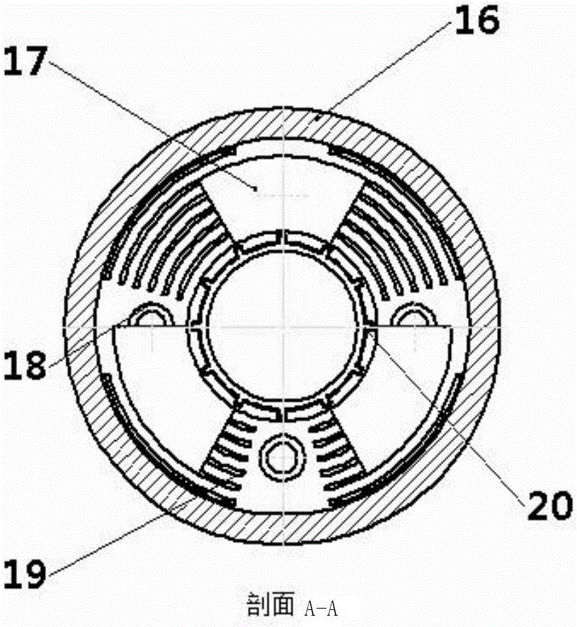
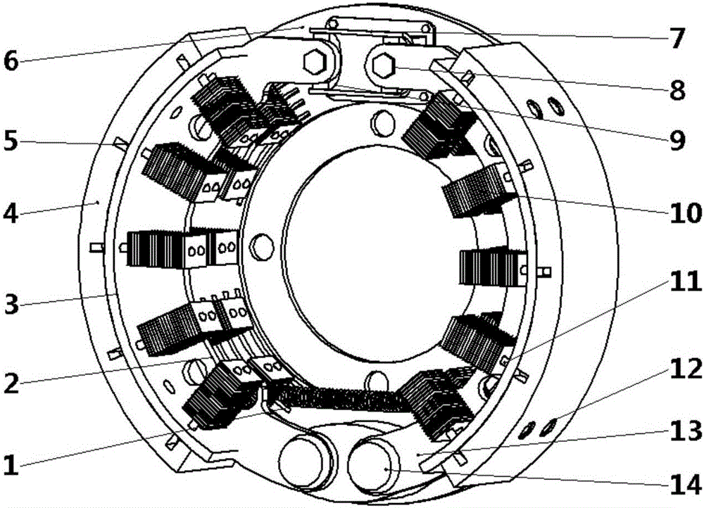
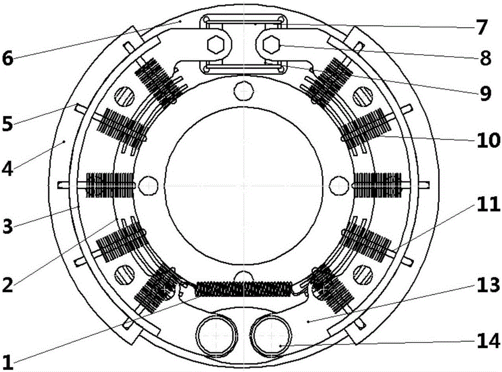
[0047] like Figure 1 to Figure 9 and Figure 14 to Figure 16 As shown, a drum brake that dissipates heat through heat pipes includes front brake shoes 2, rear brake shoes 13, friction plates 4, brake shoe return springs 1, brake wheel cylinders 7, heat pipes 11 and support pins 14 One end of the front brake shoe 2 and the rear brake shoe 13 are movably connected to the brake base plate 6 through two support pins 14 respectively, and the other ends of the front brake shoe 2 and the rear brake shoe 13 are respectively passed through the brake wheel cylinder The piston pin 8 is connected to the brake wheel cylinder piston 9, and the brake wheel cylinder piston 9 is arranged in the brake wheel cylinder 7; the brake shoe return spring 1 is respectively connected with the front brake shoe 2 and the rear brake shoe 13;

[0048] The outer circumference of the front brake shoe 2 and the rear brake shoe 13 is connected with the friction plate 4, preferably the front brake shoe 2 and t...

Embodiment 2

[0055] like Figure 10 to Figure 13 As shown, a drum brake that dissipates heat through heat pipes includes front brake shoes 2, rear brake shoes 13, friction plates 4, brake shoe return springs 1, brake wheel cylinders 7, heat pipes 11 and support pins 14 One end of the front brake shoe 2 and the rear brake shoe 13 are movably connected to the brake base plate 6 through two support pins 14 respectively, and the other ends of the front brake shoe 2 and the rear brake shoe 13 are respectively passed through the brake wheel cylinder The piston pin 8 is connected to the brake wheel cylinder piston 9, and the brake wheel cylinder piston 9 is arranged in the brake wheel cylinder 7; the brake shoe return spring 1 is respectively connected with the front brake shoe 2 and the rear brake shoe 13;

[0056] The outer circumference of the front brake shoe 2 and the rear brake shoe 13 is connected with the friction plate 4, preferably the front brake shoe 2 and the rear brake shoe 13 are p...


PUM


Abstract

The invention discloses a drum brake cooled through heat pipes. The drum brake comprises a front brake shoe, a rear brake shoe, a friction plate, a brake shoe return spring, a brake cylinder, fan blades, the heat pipes and supporting pins. The multiple heat pipes are arranged on the front brake shoe, the rear brake shoe and the friction plate in a spaced mode. A brake drum body is mounted on the periphery of the friction plate and mounted on a wheel through brake drum mounting holes. The fan blades are mounted on the brake drum body which is provided with arc vent grooves. The heat pipe array is embedded between the brake shoes of the drum brake and the friction plate, the fan blades are arranged in the brake drum, and the role of a fan is played in the vehicle running process. Through the structural features, a large amount of heat generated in mutual friction of the friction plate and the brake drum in the vehicle braking process can be quickly conducted into a brake drum chamber through the heat pipes, the heat is taken into the external environment through air flowing into the brake drum chamber, and therefore the temperature of the brake drum and the temperature of the friction plate are reduced, and the braking performance of the brake is more stable.

Description

technical field [0001] The invention relates to a vehicle brake (that is, a brake device), in particular to a rapid heat conduction through a heat pipe, so as to achieve rapid heat dissipation, avoid excessive temperature rise of drum brake components, thermal recession, and brake failure, and belong to automobiles. Spare parts technical field. Background technique [0002] To slow down or even stop a moving car, keep the speed of a downhill car stable, and keep a stopped car still, these functions are collectively called car braking. The brake is a component used in automobile braking to generate a force that hinders the movement or movement tendency of the vehicle. At present, the brakes used in all kinds of automobiles are almost all friction brakes, and the friction brakes used in automobiles can be divided into two categories: drum type and disc type. Among them, the drum brake has high braking efficiency, simple structure and flexible space arrangement, and has been ...

Claims


Application Information

Patent Timeline
Patent Type & Authority Applications(China)
IPC IPC(8): F16D65/827F16D69/02
CPCF16D65/827F16D69/02
Inventor 简弃非吴昊
Owner SOUTH CHINA UNIV OF TECH
Why Eureka
Try Eureka