Automatic locomotive air damping control method for locomotive in emergency state or power-off state and system

A control system and air brake technology, applied in the direction of brake safety system, hydraulic brake transmission device, etc., can solve the problem of difficulty in taking into account, fluctuation of locomotive brake cylinder brake pressure, and the ability of small brakes to control locomotive brake cylinder pressure. Weak and other problems, to achieve the effect of clear and simple design ideas, enhanced comprehensive control capabilities, and easy learning and mastery

Active Publication Date: 2013-09-18
徐晖
View PDF4 Cites 0 Cited by
  • Summary
  • Abstract
  • Description
  • Claims
  • Application Information

AI Technical Summary

Problems solved by technology

[0004] 1. The maximum braking pressure of the locomotive is controlled by the exhaust of the safety valve on the distribution valve, which will cause continuous fluctuations in the braking pressure of the brake cylinder of the locomotive
[0005] 2. The safety valve on the distribution valve is continuously exhausted, which is easy to cause damage to the safety valve. In actual use, the failure rate of the safety valve is very high
[0006] 3. After emergency braking, the control ability of the small brake to the brake cylinder pressure of the locomotive is very weak, and the pressure of the brake cylinder of the locomotive cannot be controlled arbitrarily
[0007] 4. After the locomotive is powered off, the total air will be exhausted continuously through the safety valve on the distribution valve, which not only wastes the air source but also affects the life of the safety valve
[0009] 1. It is not suitable to use the common braking control system of locomotives to realize the emergency braking control function of locomotives, because the time requirements are different, and it is difficult to achieve both
[0010] 2. The automatic braking of the locomotive cannot be achieved after the system loses power

Method used


Image

  • Automatic locomotive air damping control method for locomotive in emergency state or power-off state and system
  • Automatic locomotive air damping control method for locomotive in emergency state or power-off state and system
  • Automatic locomotive air damping control method for locomotive in emergency state or power-off state and system

Examples


Embodiment 1

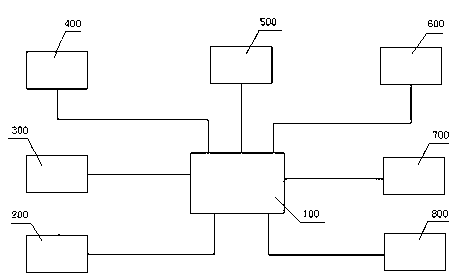
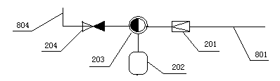
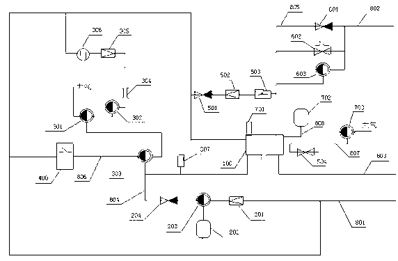
[0051] The specific example is as figure 1 , figure 2 and image 3 As shown, the distribution valve 100, the locomotive emergency or power failure automatic braking control system 200, the locomotive common braking control system 300, the small gate control system 400, the no-fire branch control system 500, the train management backup control system 600, Other standby control system 700, air pipe branch system 800, etc., constitute the distribution valve comprehensive control system.

[0052] The distribution valve 100, as a main air valve in the locomotive braking system, can perform complex air circuit control and conversion functions.

[0053] The invention described above is an emergency or power-off automatic braking control system 200 for a locomotive. Cooperating with the air duct branch system 800, the distribution valve 100 can be controlled to automatically brake the locomotive when the locomotive is in an emergency or power-off state.

[0054] Adjust the first p...


PUM


Abstract

Disclosed are an automatic locomotive air damping control method for a locomotive in an emergency state or a power-off state and a system. A distributing valve comprehensive control system is adopted in the air brake damping control system, and automatic air damping control of the railway locomotive in the emergency state or the power-off state is realized by the aid of an air channel control and conversion function of the distributing valve comprehensive control system; the distributing valve comprehensive control system comprises a distributing valve, a locomotive emergency or power-off automatic braking control system, a locomotive service braking control system, a small brake control system, a fireless branch control system, a train pipe standby control system, another standby control system and an air pipe branch system; and the locomotive emergency or power-off automatic braking control system and the air pipe branch system match with each other to realize the air channel control and conversion function, and accordingly automatic braking of the locomotive is realized by means of controlling the distributing valve when the locomotive is in the emergency state or the power-off state. Quick and automatic braking of the locomotive can be realized by means of converting and controlling valves when in the emergency state or the power-off state.

Description

technical field [0001] The present invention relates to a railway locomotive component structure, in particular to an automatic air brake control method and system device for a railway locomotive in an emergency or power-off state, and is mainly used for function improvement and promote. Background technique [0002] Among the existing railway locomotive brake systems, the domestically designed DK-1 brake machine has been used for decades, and the basic performance of its distribution valve control system has been fully tested. However, with the advancement of control technology and the continuous improvement of railway transportation requirements, there is room for improvement and improvement in the distribution valve control system, and there are some deficiencies in the braking control link in emergency or power-off conditions. [0003] 1. In the original DK-1 brake distribution valve control system, whenever there is an emergency or power failure, the pressure chamber o...

Claims


Application Information

Patent Timeline
Patent Type & Authority Patents(China)
IPC IPC(8): B60T17/18B60T11/28
Inventor 徐晖
Owner 徐晖
Why Eureka
Try Eureka