Split assembled type primary explosive-free electric detonator
A non-priming, assembly-type technology, applied in the direction of weapon accessories, fuzes, offensive equipment, etc., can solve the problems of low safety, high production cost and use cost, poor detonation ability of non-priming electric detonators, etc., to achieve safety High, low production cost and use cost, superior performance
- Summary
- Abstract
- Description
- Claims
- Application Information
AI Technical Summary
Problems solved by technology
Method used
Image
Examples
Embodiment 1
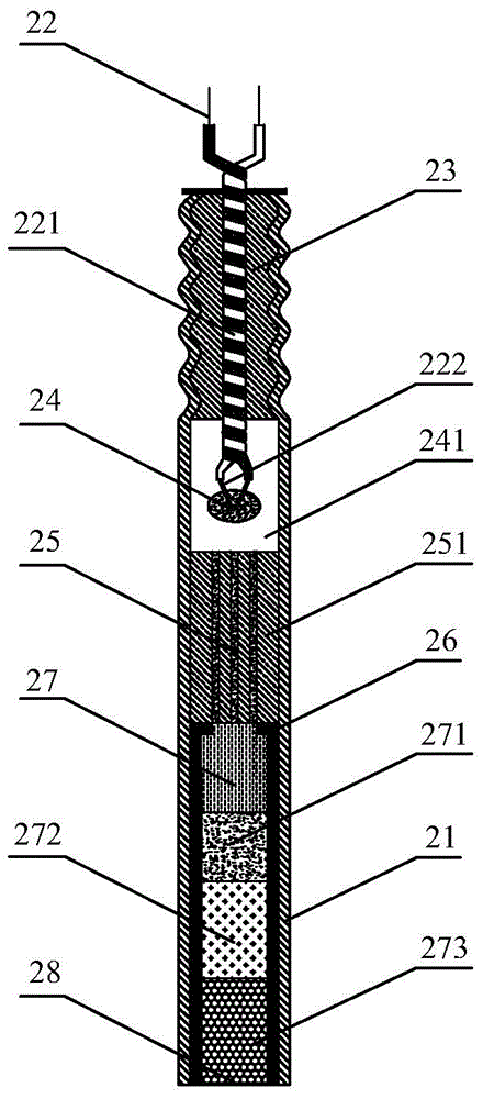
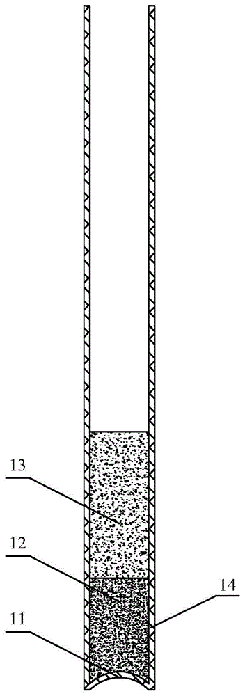
[0037] Such as figure 1 Shown is the overall structure diagram of a three-core extended body of a split assembly type non-priming charge delayed electric detonator according to the first embodiment of the present invention. As a preferred solution of the present invention, a split assembly type non-initiating charge electric detonator is designed to be composed of the detonator outer tube 14, and the main charge explosive buried in the detonator outer tube 14, and the detonator inner tube, such as figure 2 The structure diagram of the inner tube of the detonator of a three-core delayed body detonator of a split assembly type non-priming charge delayed electric detonator according to the first embodiment of the present invention is shown. The inner tube of the detonator includes a detonator inner tube shell 21, a leg wire 22, and a leg wire outer skin. 221, bridge wire 222, bayonet plug 23, charge head 24, air chamber 241, delay body, fire hole 261, detonation element and detonat...
Embodiment 2
[0048] Such as Figure 4 Shown is the overall structure diagram of a separate assembly type non-priming charge delayed electric detonator single-core delayed body of the second embodiment of the present invention. As a preferred solution of the present invention, a split assembly type non-initiating charge electric detonator is designed to be composed of the detonator outer tube 14, and the main charge explosive buried in the detonator outer tube 14, and the detonator inner tube, such as Figure 5 The structure diagram of the detonator inner tube of a separate assembly type non-initiating charge delayed electric detonator single-core delayed body detonator according to the second embodiment of the present invention is shown. The detonator inner tube includes a detonator inner tube shell 21, a leg wire 22, and a leg wire outer skin 221, bridge wire 222, bayonet plug 23, drug head 24, air chamber 241, delay body, fire hole 261, detonator element and detonator inner tube base 28, su...
Embodiment 3
[0056] Such as Figure 7 Shown is the overall structure diagram of a split assembly type instantaneous power generation detonator without detonator in the third embodiment of the present invention. As a preferred solution of the present invention, a split assembly type non-initiating charge electric detonator is designed to be composed of the detonator outer tube 14, and the main charge explosive buried in the detonator outer tube 14, and the detonator inner tube, such as Picture 8 The structure diagram of the detonator inner tube of a split assembly type instantaneous power generation detonator without detonator according to the third embodiment of the present invention is shown. The detonator inner tube includes a detonator inner tube shell 21, a leg cord 22, a leg cord outer skin 221, and a bridge wire. 222, bayonet plug 23, charge head 24, air chamber 241, fire hole 261, detonation element and detonator inner tube base 28, such as Picture 9 Shown is a structural diagram of ...
PUM
 Abstract
Description
Claims
Application Information
 - R&D
- Intellectual Property
- Life Sciences
- Materials
- Tech Scout
- Unparalleled Data Quality
- Higher Quality Content
- 60% Fewer Hallucinations
Browse by: Latest US Patents, China's latest patents, Technical Efficacy Thesaurus, Application Domain, Technology Topic, Popular Technical Reports.
© 2025 PatSnap. All rights reserved.Legal|Privacy policy|Modern Slavery Act Transparency Statement|Sitemap|About US| Contact US: help@patsnap.com


