Liquid crystal panel

A liquid crystal display panel, liquid crystal medium technology, applied in nonlinear optics, instruments, optics, etc., can solve the problems of reduced aperture ratio, pixel aperture ratio, etc., to improve the aperture ratio, avoid corner rounding, avoid light mixing phenomenon Effect

Inactive Publication Date: 2015-11-18
AU OPTRONICS CORP
View PDF5 Cites 11 Cited by
  • Summary
  • Abstract
  • Description
  • Claims
  • Application Information

AI Technical Summary

Problems solved by technology

However, in the case of shrinking pixel size, the black matrix layer in the current liquid crystal display panel is prone to corner rounding (Rounding) due to factors such as manufacturing process or material (such as figure 1 shown), which in turn leads to a decrease in the aperture ratio of the pixel
Therefore, in order to achieve high-resolution liquid crystal display panels, how to avoid the reduction of aperture ratio under the premise of effectively shielding the internal wiring of the liquid crystal display panel is an important issue that must be overcome.

Method used


Image

  • Liquid crystal panel
  • Liquid crystal panel
  • Liquid crystal panel

Examples


Embodiment Construction

[0066] The present invention will be described in detail below in conjunction with the accompanying drawings and specific embodiments, but not as a limitation of the present invention.

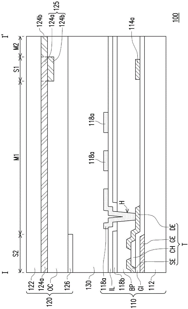
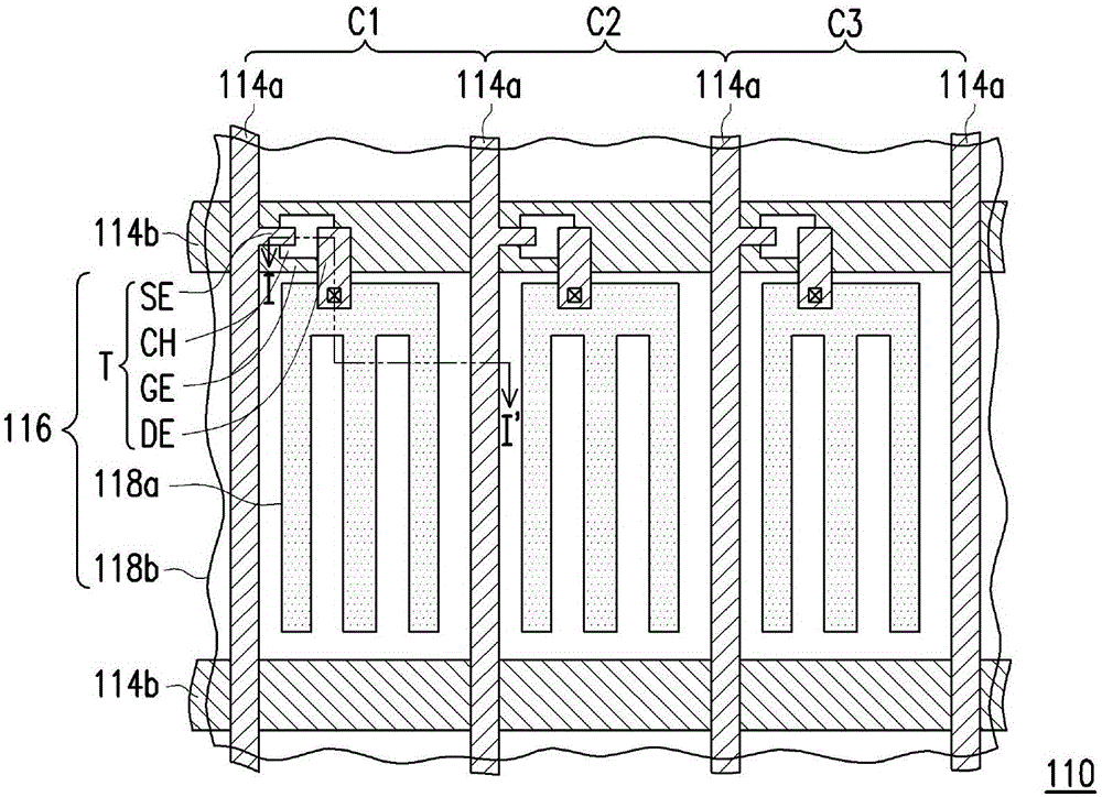
[0067] figure 2 is a schematic cross-sectional view of a liquid crystal display panel according to an embodiment of the present invention. image 3 for figure 2 A partial top view of the pixel array substrate in Fig. Figure 4 for figure 2 Schematic diagram of a partial top view of a medium-color filter substrate. Figure 5 is along Figure 4 The cross-sectional schematic diagram of the section line A-A' in . Figure 6 is along Figure 4 A schematic cross-sectional view of the section line B-B' in . Figure 7 is along Figure 4 The cross-sectional schematic diagram of the section line C-C' in . in addition, figure 2 The cross-section position corresponds to image 3 and Figure 4 The position of section line I-I' in . In the following, the figure 2 , image 3 , Figure 4 , ...


PUM


Abstract

The invention discloses a liquid crystal display panel comprising a first substrate and a second substrate, a plurality of signal cables, a plurality of pixel structures, a first color filtering pattern layer, a second color filtering pattern layer and a third color filtering pattern layer, a shading pattern layer and liquid crystal medium. The second substrate is provided with a plurality of a first and a second shading areas, a plurality of a first transmission area, a second transmission area and a third transmission area, and the first and second shading areas defines the first, the second and the third transmission area. A first color fitering pattern layer is correspondingly arranged in the first transmission area and the first shading area; the second color filtering pattern layer is arranged in the second transmission area and the first shading area; and the first color filtering pattern layer stacks with each other in the first shading area. The third color filtering pattern layer is corrsondingly arranged in the third transmission area. The shading pattern layer is corresondingly arranged in the second shading area and on the first, the second and the third color filtering pattern layers.

Description

technical field [0001] The present invention relates to a display panel, and in particular to a liquid crystal display panel. Background technique [0002] With the development of liquid crystal display panels, high resolution has become one of the basic requirements. In current liquid crystal display panels, high resolution is usually achieved by reducing the pixel size. However, in the case of shrinking pixel size, the current black matrix layer in the liquid crystal display panel is prone to corner rounding (Rounding) due to factors such as manufacturing process or material (such as figure 1 shown), which in turn leads to a decrease in the aperture ratio of the pixel. Therefore, in order to achieve high resolution of the liquid crystal display panel, how to avoid the reduction of the aperture ratio under the premise of effectively shielding the internal traces of the liquid crystal display panel is an extremely important issue to be overcome. Contents of the invention...

Claims


Application Information

Patent Timeline
Patent Type & Authority Applications(China)
IPC IPC(8): G02F1/1335G02F1/1362
CPCG02F1/133509G02F1/133512G02F1/136286G02F2201/40G02F1/133514
Inventor 叶碧纯郑景升
Owner AU OPTRONICS CORP
Why Eureka
Try Eureka