Power bank and charging box employing same
A mobile power supply and charging box technology, which is applied to battery circuit devices, current collectors, electric vehicles, etc., can solve the problems of inconvenient carrying, large volume and heavy weight of mobile power supplies, and achieve safe and convenient use, small size and light weight Effect
- Summary
- Abstract
- Description
- Claims
- Application Information
AI Technical Summary
Problems solved by technology
Method used
Image
Examples
Embodiment 1
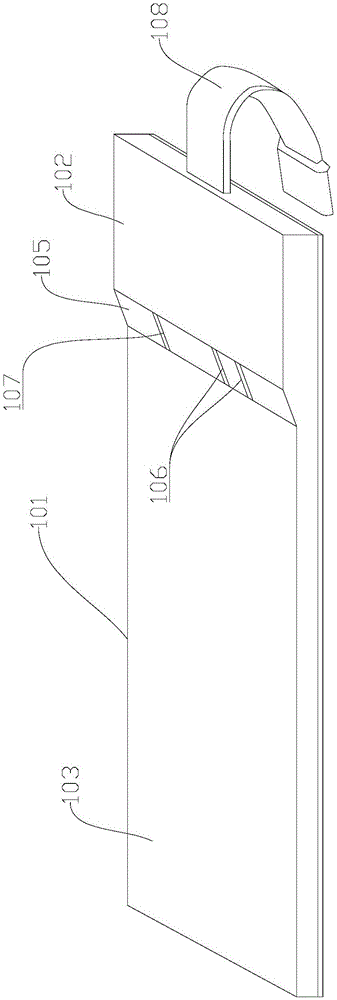
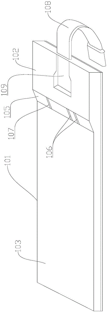
[0042] see figure 1 and figure 2 As shown, Embodiment 1 of the present invention provides a mobile power supply, including a battery 101 and a circuit module 102. Specifically, the thickness of the battery 101 is 2mm-3mm, the thickness of the circuit module 102 is 2mm-5.5mm, and the thickness of the battery 101 The capacity is 500mAh-600mAh; the battery 101 is electrically connected to the circuit module 102; the battery 101 is plate-shaped, and the battery 101 includes a first board surface 103 and a second board surface; the circuit module 102 is arranged on the first board surface 103, and the circuit module 102 A first charging interface and a second charging interface 106 are provided; the first charging interface is used to charge the mobile phone through the battery 101 after being connected to the mobile phone; the second charging interface 106 is used to connect the external power supply to the battery 101 for charging; the second board is used to fit on the phone. ...
Embodiment 2
[0047] see image 3 As shown, the second embodiment of the present invention provides a mobile power supply, including a battery 101 and a circuit module 102. Specifically, the thickness of the battery 101 is 2mm-3mm, the thickness of the circuit module 102 is 2mm-5.5mm, and the thickness of the battery The capacity is 500mAh-600mAh; the battery 101 is electrically connected to the circuit module 102; the battery 101 is plate-shaped, and the battery 101 includes a first board surface 103 and a second board surface; the circuit module 102 is arranged on the first board surface 103, and the circuit module 102 A first charging interface and a second charging interface 106 are provided; the first charging interface is used to charge the mobile phone through the battery 101 after being connected to the mobile phone; the second charging interface 106 is used to connect the external power supply to the battery 101 for charging; the second board is used to fit on the phone. The mobil...
Embodiment 3
[0053] see Figure 4 to Figure 7 As shown, the third embodiment provides a charging box, including a box body 110 and at least one mobile power supply provided in the first or second embodiment; the mobile power supply is provided in the box body 110 .
[0054] In the third embodiment, the box body 110 is provided with at least one slot 111, that is to say, the slot 111 is arranged inside the box body 110; the mobile power supply is inserted in the slot 111; The charging output port connected to the second charging interface 106, specifically, the charging output port is a contact piece, so that when the mobile power supply is inserted into the slot 111, the second charging interface 106 is docked with the charging output port, so that the mobile power supply can be connected to the charging output port. Power charging. It should be noted that, in the third embodiment, the way of inserting the mobile power supply into the slot 111 can be vertical insertion or side insertion; ...
PUM
 Abstract
Description
Claims
Application Information
 - R&D
- Intellectual Property
- Life Sciences
- Materials
- Tech Scout
- Unparalleled Data Quality
- Higher Quality Content
- 60% Fewer Hallucinations
Browse by: Latest US Patents, China's latest patents, Technical Efficacy Thesaurus, Application Domain, Technology Topic, Popular Technical Reports.
© 2025 PatSnap. All rights reserved.Legal|Privacy policy|Modern Slavery Act Transparency Statement|Sitemap|About US| Contact US: help@patsnap.com


