
Electronic device and key mounting structure

A technology for installation structure and keys, which is applied in the structure of telephone sets, branch office equipment, circuits, etc. It can solve the problems of easy loose keys and easy warping of users' physical examination, and achieve the effect of solving shaking and abnormal noise and improving experience comfort

Inactive Publication Date: 2015-11-18
GUANGDONG OPPO MOBILE TELECOMM CORP LTD
View PDF5 Cites 5 Cited by
  • Summary
  • Abstract
  • Description
  • Claims
  • Application Information

AI Technical Summary

Problems solved by technology

[0005] The purpose of the present invention is to overcome the defects of the prior art and provide a button installation structure to solve the problems of the prior art that the buttons are easy to loosen, easily warp and the user's physical inspection is poor

Method used


Image

  • Electronic device and key mounting structure
  • Electronic device and key mounting structure
  • Electronic device and key mounting structure

Examples


Embodiment Construction

[0024] In order to make the object, technical solution and advantages of the present invention clearer, the present invention will be further described in detail below in conjunction with the accompanying drawings and embodiments. It should be understood that the specific embodiments described here are only used to explain the present invention, not to limit the present invention.

[0025] The embodiment of key installation structure:

[0026] see Figure 1 to Figure 7 , the best embodiment of the key installation structure of the present invention will be described below.

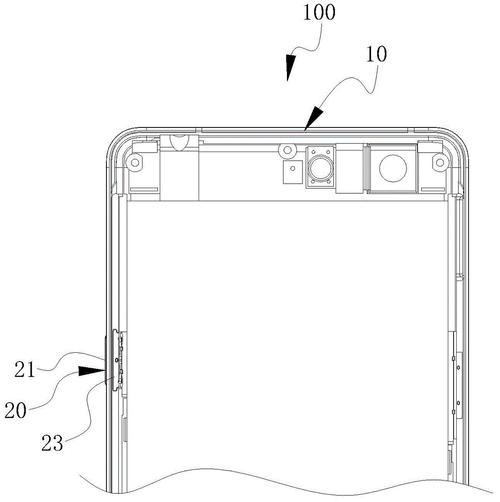
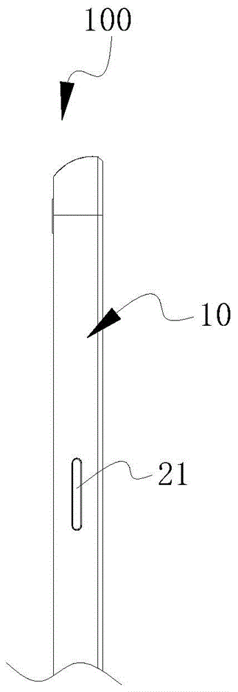
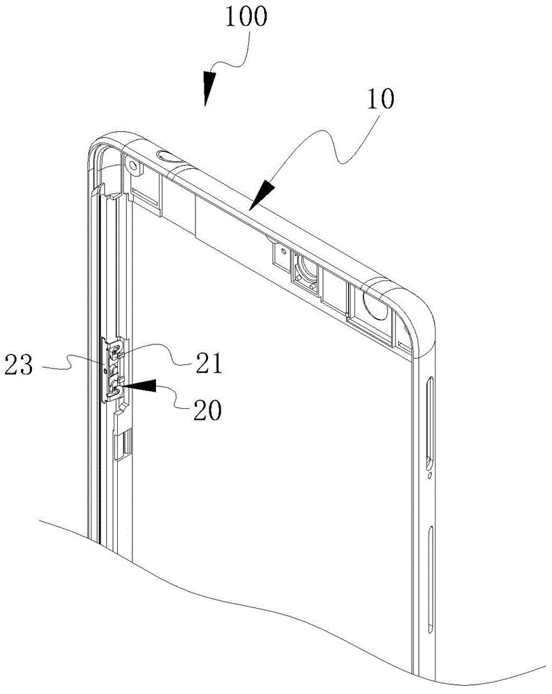
[0027] The electronic device 100 of this embodiment can be electronic products such as mobile phones, MP3, MP4, and tablet computers. The electronic device 100 includes a button installation structure 20, and the button installation structure 20 includes a shell 10, a button 21 and an elastic pressing member 23. Facing each part of this key installation structure 20, make further explanation:

[0028]...


PUM


Abstract

The invention provides a side button mounting structure of electronic equipment. The side button mounting structure comprises a side button, a button mounting hole and an elastic compression component, wherein the button mounting hole is formed in the side end of a shell of the electronic equipment; the side button is arranged in the button mounting hole; the elastic compression component is arranged on the side end of the shell, is close to the position of the button mounting hole and comprises a fixing part and a pressing part which is connected with the fixing part; the fixing part is connected and fixed to the side end of the shell; the pressing part is bent to go into the button mounting hole and is connected to the side button. The side button mounting structure provided by the invention is provided with the elastic compression component and is connected and fixed to the side end of the shell through the fixing part of the elastic compression component, and the pressing part of the elastic compression component is bent to go into the button mounting hole and is connected to the side button, so that the button is enabled not to come off outwards, certain pressing elasticity of two ends of the side button is also guaranteed, and the problem that a side button of electronic equipment swings and gives abnormal noise in the prior art is better solved. The invention also provides the electronic equipment.

Description

technical field [0001] The invention relates to the technical field of electronic equipment, in particular to an electronic equipment and a button installation structure. Background technique [0002] In current electronic equipment, especially mobile phones, there are generally two ways to install the keys of the mobile phone: the first one, the keys are installed from the inside to the outside from the key mounting holes on the inner wall of the mobile phone housing; The button mounting holes are installed from the outside to the inside. [0003] Wherein, for a single-contact button installed from outside to inside (such as a power button), the button contact is arranged at the middle position of the button, and the button contact is in contact with the switch on the circuit board to realize the pressing operation. However, if there is a gap between the key contact and the switch contact surface due to assembly problems, the key will become loose, and as long as the mobil...

Claims


Application Information

Patent Timeline
Patent Type & Authority Applications(China)
IPC IPC(8): H04M1/02H04M1/23H04M1/725
CPCH01H13/12H01H2231/022
Inventor 肖中华
Owner GUANGDONG OPPO MOBILE TELECOMM CORP LTD
Learn More