
PCB carrier

A technology of circuit boards and carriers, applied in the field of carriers, can solve the problems of difficult removal of circuit boards, waste of working hours and procedures, damage of circuit boards, etc.

Inactive Publication Date: 2016-04-06
LEXTAR ELECTRONICS CORP
View PDF3 Cites 0 Cited by
  • Summary
  • Abstract
  • Description
  • Claims
  • Application Information

AI Technical Summary

Problems solved by technology

[0004] Although the above-mentioned conventional substrates can be used to carry circuit boards and be covered with double-sided adhesive tape for surface-mounting process, since the double-sided adhesive tape is arranged on the plane of one side of the substrate, the bonding between the circuit board and the substrate is difficult. The cover is larger and the stickiness is stronger. Therefore, when the circuit board is removed from the substrate after the surface-mounting technology process, there will often be residual double-sided adhesive on the circuit board, and the circuit board needs to be removed afterwards. If the circuit board is a flexible board, it will cause the circuit board Difficult to remove, or circuit board damage due to improper application of force during removal

Method used


Image

  • PCB carrier
  • PCB carrier
  • PCB carrier

Examples


Embodiment Construction

[0041] The spirit of the present invention will be described in detail with the accompanying drawings. Anyone with ordinary knowledge in the technical field can change and modify it by the technology taught in the present invention after understanding the preferred embodiments of the present invention without departing from it. spirit and scope of the invention.

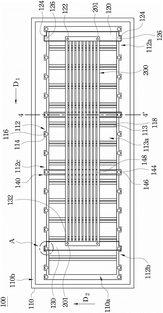
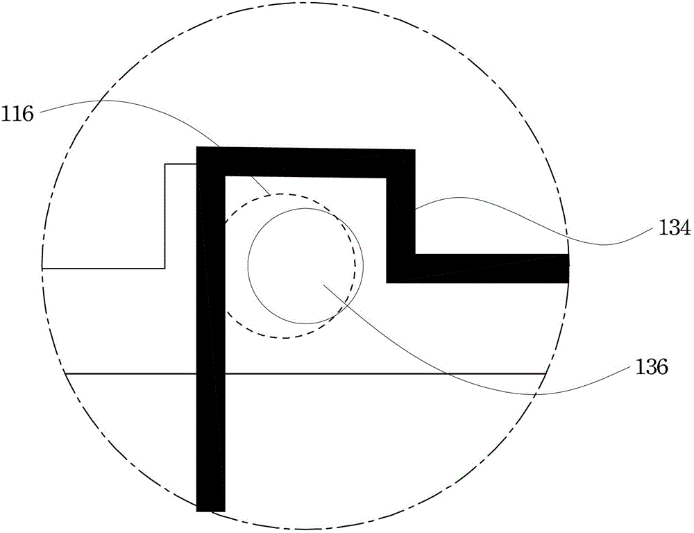
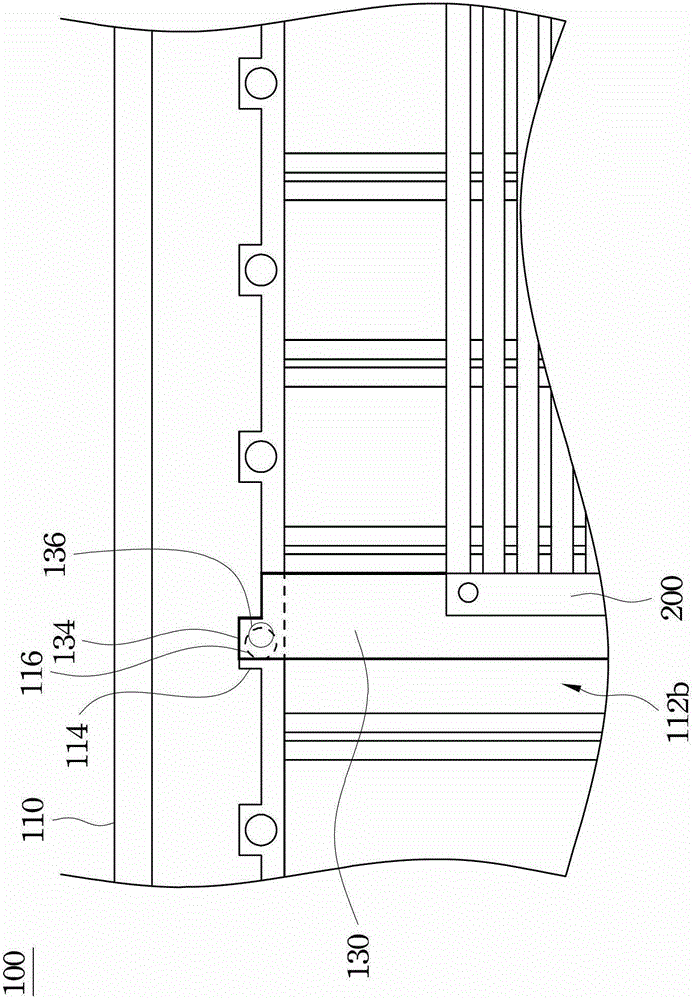
[0042] Please refer to figure 1 as well as Figure 1A , figure 1 A top view of a circuit board carrier 100 according to an embodiment of the present invention is shown. Figure 1A A partially enlarged view of part A of a circuit board carrier according to an embodiment of the present invention is shown. Such as figure 1 as well as Figure 1A As shown, the circuit board carrier 100 may include a carrier 110 , a fixing member 120 and a tension member 130 .

[0043] The carrier 110 can be divided into an accommodating groove area 110a and a non-accommodating groove area 110b, and the non-accommodating groove area ...


PUM


Abstract

The invention discloses a circuit board carrier comprising a carrying body, a fixing piece and a pull piece. The carrying body has multiple acommodation grooves. Two opposite sides of each accommodation groove are each provided with a first clamping groove, and a first magnetic piece is disposed inside each first clamping groove. In addition, the bottom of each accommodation groove is a frame body with an opening, and the surface of the bottom of each accommodation groove is lower than the surface of a non-accommodation groove area. The fixing piece is placed in the first acommodation groove and has a first positioning portion used for fixing one end of a circuit board extending in a first direction. The pull piece has a second positioning portion used for fixing the other end of the circuit board. Third magnetic pieces at two end portions of the pull piece ovelap the first magnetic piece inside the first clamping groove of the second accommodation groove, so that magnetic pull forces far away from the fixing piece are produced.

Description

technical field [0001] The present invention relates to a carrier, and in particular to a circuit board carrier. Background technique [0002] At present, the method of mounting electronic parts on the circuit board mainly utilizes surface mount technology (SMT) for bonding. The joining method of the surface mount technology is to use solder paste to directly join the lead end of the electronic component to the pad on the surface of the circuit board without penetrating the circuit board. In the above-mentioned implanting process, the circuit board must be carried by the circuit board carrier and pass through the tin furnace, so that the solder paste becomes liquid after being heated by the tin furnace, and surrounds the leads of the electronic parts and the pads of the circuit board. . Then, when the liquid tin is cooled and solidified, the solid tin can fix the lead pins of the electronic components on the circuit board and at the same time electrically connect with the ...

Claims


Application Information

Patent Timeline
Patent Type & Authority Patents(China)
IPC IPC(8): H05K3/34
Inventor 杨振明
Owner LEXTAR ELECTRONICS CORP
Learn More