Operating-fluid container

A technology for working fluids and containers, which can be used in household components, substructures, applications, etc., and can solve problems such as occupying the internal volume of containers

Active Publication Date: 2015-11-18
KAUTEX TEXTRON
View PDF10 Cites 5 Cited by
  • Summary
  • Abstract
  • Description
  • Claims
  • Application Information

AI Technical Summary

Problems solved by technology

However, these measures have the disadvantage that they come a

Method used


Image

  • Operating-fluid container
  • Operating-fluid container
  • Operating-fluid container

Examples


Embodiment Construction

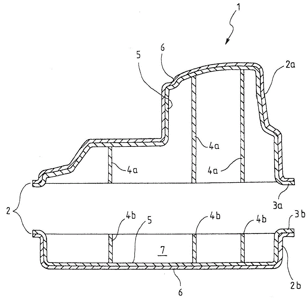
[0028] The working fluid container 1 according to the invention is basically assembled from two injection molded shells 2a, 2b, wherein the shell 2a forms the upper shell of the working fluid container 1 and the shell 2b forms the lower shell. The housings in each case form a peripherally surrounding flange 3a, 3b where the housings 2 are welded to each other to form a closed working fluid container. Each housing 2 has been obtained by co-injection molding, wherein in accordance with figure 1 In the exemplary embodiment shown, both the upper and lower housings have in each case a one-piece molded structure, for example in the form of a partition wall element 4a, 4b.

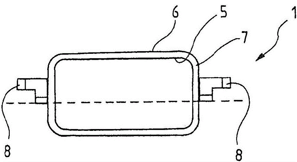
[0029] exist figure 1 In the exemplary embodiment of the invention shown in , the housing 2 is in each case formed in two layers, comprising an inner layer 5 and an outer layer 6 . These layers are made of different thermoplastic materials with different strengths and / or different molecular structures. The mul...


PUM


Abstract

The invention relates to an operating-fluid container (1) for a motor vehicle, comprising a container body which is assembled from two mutually complementary injection-moulded shells (2a, 2b) which consist of thermoplastic material and are welded together in an encircling manner to form a substantially closed hollow body, wherein at least one shell (2a, 2b) is at least in regions formed from thermoplastic materials having different strengths, wherein at least one part-region consists of a thermoplastic material having a fibrous filling, wherein the shell (2a, 2b) has been obtained by way of a co-injection process during injection moulding.

Description

technical field [0001] The invention relates to a working fluid container for a motor vehicle comprising a container body assembled from at least two complementary injection molded shells made of thermoplastic material and welded in a circumferential manner together to form a substantially closed hollow body. Background technique [0002] An injection molded container of this type is disclosed, for example, in DE 19909041 A1. EP0775606A2 discloses an injection-molded container assembled from two container halves, which in each case have been produced by injection moulding. Finally, a container assembled from injection molded half-shells is disclosed in US 5,398,839. This US patent document describes an injection-moulded fuel tank assembled from two multi-layer half-shells using in each case an inner shell and An outer casing is assembled. [0003] In the sense of the present invention, a working fluid container is a non-stationary container for a motor vehicle, such as a...

Claims


Application Information

Patent Timeline
IPC IPC(8): B60K15/03B29C45/00B60K13/04B60K15/077
CPCB60K15/03177B29C45/1642B29C2045/1692B29L2031/7172B60K13/04B60K2015/03032B60K2015/03046B60K2015/03375B60K2015/0344B60K2015/0346B60K2015/03493B60K2015/0775B60K2015/0777
Inventor H·吕恩N·舒马赫
Owner KAUTEX TEXTRON
Why Eureka
Try Eureka