Stacked heat exchanger
A heat exchanger, stacked technology, used in heat exchange equipment, heat exchanger shells, indirect heat exchangers, etc. characteristics and pressure loss characteristics
- Summary
- Abstract
- Description
- Claims
- Application Information
AI Technical Summary
Problems solved by technology
Method used
Image

Examples
no. 1 Embodiment approach
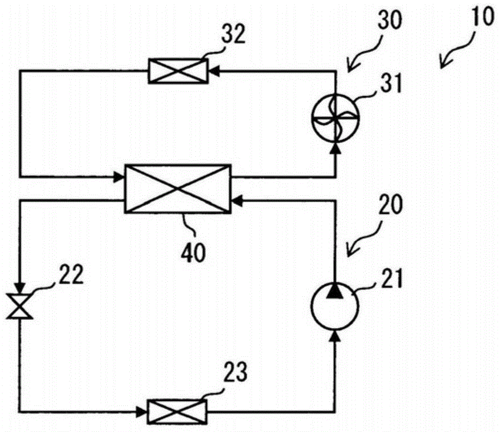
[0066] Such as figure 1 As shown, the first embodiment discloses a thermal system 10 . The thermal system 10 is mounted on a vehicle. The thermal system 10 provides an air conditioner for a vehicle or a temperature adjustment device for equipment mounted on a vehicle. When utilized as an air conditioner, thermal system 10 provides heating and / or cooling. When utilized as a thermostat, thermal system 10 provides a heat source for heating and / or a low temperature source for cooling. The thermal system 10 has a refrigeration circuit 20 . The refrigeration cycle 20 is a vapor compression type refrigeration cycle 20 that provides low temperature and high temperature by compressing refrigerant vapor. The refrigerant is also referred to as the first heating medium. Further, the thermal system 10 has an auxiliary system 30 through which a heat carrier that exchanges heat with the refrigerant of the refrigeration cycle 20 flows. The auxiliary system 30 circulates cooling water as...
no. 2 Embodiment approach
[0104] This embodiment is a modified example based on the previous embodiment. In the above-described embodiment, convection is formed in the entirety of the inside of the core portion 41 . In this embodiment, instead, convection is formed in a part of the inside of the core 41 .
[0105] Such as Figure 9 As shown, the heat exchanger 40 has a connection member 245 as an inlet of water and a connection member 246 as an outlet of water on one end surface. The connection member 245 and the connection member 246 are arranged at corners located on the diagonal line of the upper end surface in the figure. These connection members 245, 246 extend in parallel. The connection members 43 and 44 are respectively arranged in a dispersed manner on both end surfaces of the core portion 41 . The connecting members 43 and 44 are collectively arranged on one side in the lateral direction. Furthermore, in this embodiment, the division board 241c is used.
[0106] Such as Figure 10 As s...
no. 3 Embodiment approach
[0109] This embodiment is a modified example based on the previous embodiment. In the above-described embodiment, the partition plates 41c, 241c are used. In this embodiment, no compartmentalized panels are used.
[0110] Such as Figure 11 As shown, the heat exchanger 40 has a connection member 43 and a connection member 46 on one end surface. Furthermore, the heat exchanger 40 has a connection member 245 and a connection member 344 serving as an outlet of the refrigerant on the other end surface. In this embodiment, no compartmentalized panels are used. Therefore, all of the plurality of passages 41rf formed in the core 41 are connected in parallel between the connecting members 43 and 344 . Since the connecting members 43 and 344 are dispersedly arranged on both surfaces, an S-shaped refrigerant flow path is formed in the core 41 . All of the plurality of passages 41wt formed in the core 41 are connected in parallel between the connection members 245 and 46 . Since th...
PUM
 Abstract
Description
Claims
Application Information
 - R&D
- Intellectual Property
- Life Sciences
- Materials
- Tech Scout
- Unparalleled Data Quality
- Higher Quality Content
- 60% Fewer Hallucinations
Browse by: Latest US Patents, China's latest patents, Technical Efficacy Thesaurus, Application Domain, Technology Topic, Popular Technical Reports.
© 2025 PatSnap. All rights reserved.Legal|Privacy policy|Modern Slavery Act Transparency Statement|Sitemap|About US| Contact US: help@patsnap.com