
sulfur lamp

A technology of sulfur lamps and lamps, applied in the field of lighting devices, can solve the problems of large sulfur lamps, short nominal life, microwave leakage, etc.

Inactive Publication Date: 2018-09-14
朴秀用
View PDF6 Cites 0 Cited by
  • Summary
  • Abstract
  • Description
  • Claims
  • Application Information

AI Technical Summary

Problems solved by technology

However prior art sulfur lamp assemblies are too large to fit into the many existing lamp assemblies of many specific light fixtures for specific applications; The described magnetrons have a far shorter nominal life and thus require maintenance which requires disassembly of the entire unit and produces significant undesired microwave leakage

Method used

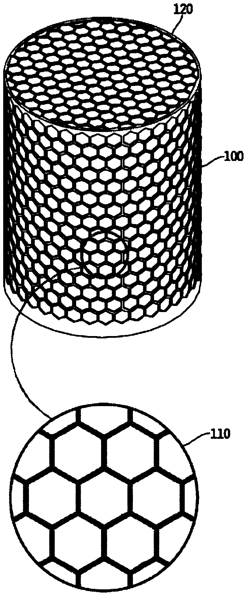
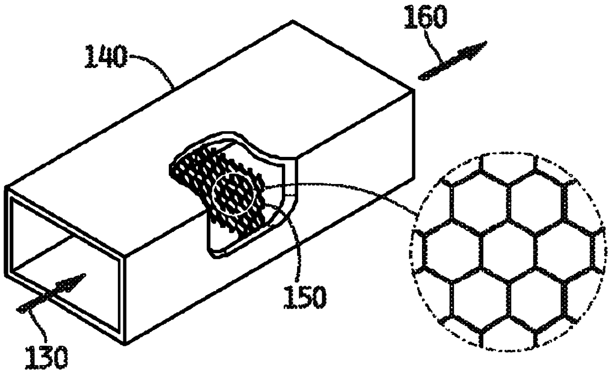
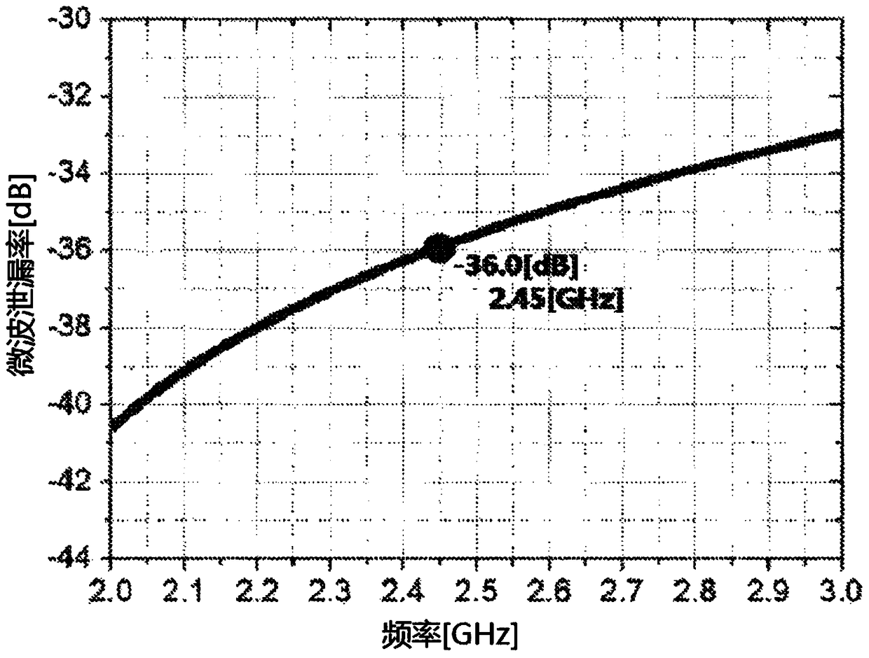

Image

  • sulfur lamp
  • sulfur lamp
  • sulfur lamp

Examples


Embodiment Construction

[0069] It should be understood that the drawings and descriptions provided herein may have been simplified to illustrate elements for a clear understanding of the present invention, while for clarity purposes, other elements found in typical similar devices, systems and methods have been deleted. Accordingly, those skilled in the art will recognize that other elements and / or steps may be desirable and / or necessary to implement the apparatus systems and methods described herein. However, since these elements and steps are known in the art and they do not contribute to a better understanding of the present invention, a discussion of these elements and steps may not be provided here. The present disclosure is considered to inherently include all such elements, variations, and modifications of disclosed elements and methods known to those skilled in the art.

[0070] Louver structure

[0071] Microwaves in a cage including conductive walls have a special electromagnetic field dis...


PUM


Abstract

The present invention discloses a sulfur lamp with low microwave leakage, comprising a structure prepared from a plurality of conductive strips. The lamp cage is removably joined together from the respective halves and is configured to be at the frequency of microwaves generated by the magnetron to induce wall currents parallel to those formed by joining the halves together. The mode resonance of the joint.

Description

[0001] Cross References to Related Applications [0002] This application claims priority from the following applications: U.S. Provisional Application No. 61 / 771549, filed March 1, 2013, titled Sulfur Lamp Cage with Low Microwave Leakage; U.S. Provisional Application No. 61 / 771569, filed March 1, 2013, the name of the invention is a separate integrated sulfur lamp; U.S. provisional application, application number 61 / 771576, filed March 1, 2013, the name of the invention is a sulfur lamp coupler; U.S. Provisional Application, application number 61 / 779097, filing date March 13, 2013, the name of the invention is a sulfur lamp coupler; U.S. provisional application, application number 61 / 771584, filing date March 1, 2013, the name of the invention is road lighting Use a sulfur lamp. [0003] This application is related to a PCT application entitled "Magnetron", filed on the same date as this application by the inventor of this application. technical field [0004] The present ...

Claims


Application Information

Patent Timeline
Patent Type & Authority Patents(China)
IPC IPC(8): H05B6/76
CPCH01J65/044H01P3/12G21F7/03G06F30/00H01J23/38
Inventor 朴秀用
Owner 朴秀用
Learn More