Flat tube discharging mechanism

A flat tube and rotating device technology, applied in metal processing, metal processing equipment, manufacturing tools, etc., can solve the problems of slow discharge of flat tubes, damage to flat tubes, low work efficiency, etc., to improve work efficiency and achieve synchronization The effect of simplifying the discharge mechanism

Active Publication Date: 2015-11-25
SHANGHAI HEKE EQUIP MFG
View PDF8 Cites 2 Cited by
  • Summary
  • Abstract
  • Description
  • Claims
  • Application Information

AI Technical Summary

Problems solved by technology

Most of the current solutions are to use the flat tube to be directly pushed out horizontally or roll out the flat tube through a cylindrical wheel. However, with the improvement of the flat tube conveying speed and

Method used


Image

  • Flat tube discharging mechanism
  • Flat tube discharging mechanism
  • Flat tube discharging mechanism

Examples


Example Embodiment

[0023] In order to make the object, technical solution and advantages of the present invention clearer, various embodiments of the present invention will be described in detail below in conjunction with the accompanying drawings. However, those of ordinary skill in the art can understand that, in each implementation manner of the present invention, many technical details are provided for readers to better understand the present application. However, even without these technical details and various changes and modifications based on the following implementation modes, the technical solution claimed in each claim of the present application can be realized.

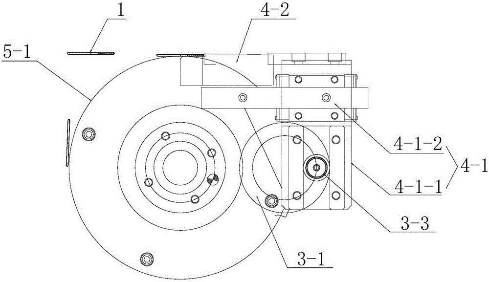
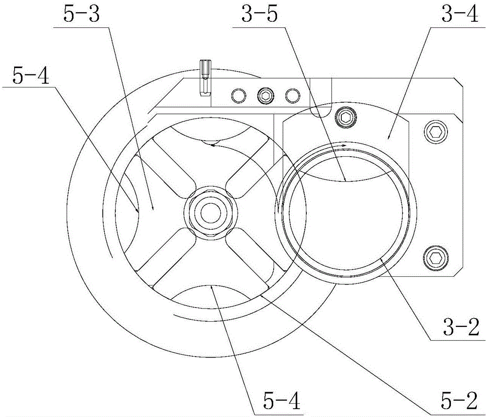
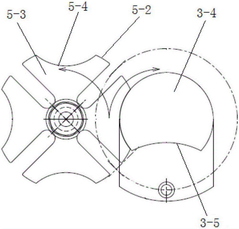
[0024] The first embodiment of the present invention relates to a flat tube discharge mechanism, such as figure 1 and figure 2 As shown, it includes a rotating device for discharging the flat tubes 1, a conveying device for sequentially feeding each flat tube 1 in the storage part (not shown in the figure) into the rotatin...


PUM


Abstract

The invention relates to a flat tube discharging mechanism which comprises a rotating device, a conveying device and a driving device, wherein the driving device comprises a transmission shaft, a synchronous wheel, a cam and a clamping block. The synchronous wheel is arranged on the transmission shaft in a sleeving mode and drives the transmission shaft to rotate, the cam is eccentrically arranged on the transmission shaft and drives the conveying device to move front and back, and the clamping block is arranged on the transmission shaft in a sleeving mode and drives the rotating device to rotate. When the cam drives the conveying device to move forwards, a flat tube located at a discharging opening of a storage portion is gradually sent onto the rotating device, and when the cam drives the conveying device to move backwards, the clamping block drives the rotating device to rotate so as to discharge the flat tube which is currently located on the rotating device. Compared with the prior art, due to the fact that the cam and the clamping block are both arranged on the transmission shaft, the conveying device and the rotating device can synchronously move, and while the whole discharging mechanism is simplified, synchronism of the conveying device and the rotating device in movement is achieved, and the work efficiency of the whole discharging mechanism is improved.

Description

technical field [0001] The invention relates to a heat exchanger flat tube production equipment, in particular to a flat tube discharge mechanism. Background technique [0002] Flat tube heat exchanger is an energy-saving equipment that realizes heat transfer between materials between two or more fluids at different temperatures. It transfers heat from a higher fluid to a lower temperature fluid, so that the fluid temperature reaches It is one of the main equipment to meet the requirements of the process conditions and improve the energy utilization rate at the same time. It can be mainly used in petroleum, chemical industry, metallurgy, electric power, shipbuilding, central heating, refrigeration and air conditioning, machinery, food, pharmaceutical and other fields. [0003] When the flat tube heat exchanger is assembled, the flat tubes are generally listed in the storage part, and discharged one by one through the discharge device, and the follow-up equipment completes t...

Claims


Application Information

Patent Timeline
IPC IPC(8): B23P19/00
CPCB23P19/004
Inventor 邢加俊任志强
Owner SHANGHAI HEKE EQUIP MFG
Why Eureka
Try Eureka