Clamp for grinding of external spherical surface of spherical surface washer

A spherical gasket and outer spherical technology, applied in spherical grinder, grinding workpiece support, grinding/polishing equipment, etc., can solve the problem of insufficient clamping force of spherical gasket, easy to throw out of spherical gasket, and no way to use grinding Machining, etc.

Inactive Publication Date: 2015-11-25
RUIAN VEHICLE FITTING FACTORY
View PDF10 Cites 1 Cited by
  • Summary
  • Abstract
  • Description
  • Claims
  • Application Information

AI Technical Summary

Problems solved by technology

The invention patent of patent No. 200810121605.0 and the patent name "Jig for Grinding Spherical Gaskets" applied by our company on October 11, 2008 has solved the above problems well, but the disadvantage is that for some spherical surfaces that are not magnetically adsorbed For gaskets (such as brass materials, powder metallurgy materials), there is no way to use the above patented technology to implement grinding
In view of this, the company later adopted a variety of solutions and designed a variety of grinding fixtures, but basically the spherical gasket is clamped from the inner hole of the spherical gasket, although it is also designed from the spherical gasket The grinding fixture for clamping the spherical gasket on the outer circumference, such as the patent No. 201310354939.3 and the patent name "spherical gasket and jig for grinding spherical gasket" applied on August 15, 2013, but obviously for the spherical gasket The clamping strength of the sheet is not enough, and the spherical gasket is easy to be thrown out during the grinding process, which poses a great safety hazard

Method used


Image

  • Clamp for grinding of external spherical surface of spherical surface washer

Examples


Embodiment Construction

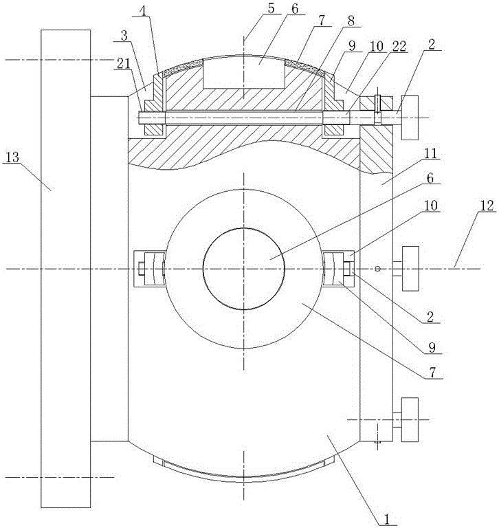
[0010] As shown in the figure, the spherical gasket outer spherical surface grinding fixture of the present invention includes a fixedly connected flange 13 and a chuck 1, the chuck 1 has a spherical arc surface with the same curvature as the inner spherical surface of the spherical gasket 7, and the chuck 1 The spherical arc is provided with four positioning pins 6 (the number of positioning pins can be arranged according to the actual situation). The axis 5 of the positioning pins 6 passes through the center of the spherical surface of the chuck 1 and is perpendicular to the rotation axis 12 of the fixture. The outer diameter of the positioning pins 6 Matching the diameter of the inner hole of the spherical gasket 7, the left clamping block 4 and the right clamping block 9 are arranged on both sides of the positioning pin 6, and the spherical arc surface of the chuck 1 is provided with a left concave cavity 3 corresponding to the left and right clamping blocks. The right cavi...


PUM


Abstract

The invention discloses a clamp for grinding of the external spherical surface of a spherical surface washer. The clamp comprises a flange plate and a chuck which are fixedly connected, the chuck is provided with a spherical cambered surface, and a plurality of positioning pins are arranged on the spherical cambered surface. The clamp is characterized in that left and right clamping blocks are arranged on the two sides of a positioning pin; a left cavity corresponding to the left clamping block and a right cavity corresponding to the right clamping block are formed in the spherical cambered surface of the chuck; the left clamping block is movably arranged in the left cavity, and the right clamping block is movably arranged in the right cavity; the head portions of the left and right clamping blocks are higher than the spherical cambered surface of the chuck; the outer end face of the chuck is fixedly connected with a flange cover; an adjusting screw is arranged on the outer end face of the flange cover in a rotating manner; a through hole is formed in the portion, between the left cavity and the right cavity, of the chuck, and the adjusting screw movably penetrates the through hole; and the adjusting screw is provided with a left-hand thread connected with the left clamping block and a right-hand thread connected with the right clamping block. By means of the clamp, the spherical surface washer can be quickly clamped and reliably fixed, grinding equipment can conduct finish machining on the spherical surface washer conveniently, and the working efficiency is improved.

Description

technical field [0001] The invention relates to a fixture, in particular to a fixture for grinding the outer spherical surface of a spherical gasket. Background technique [0002] The spherical gasket is a circular ring body with inner and outer spherical surfaces. The key of the spherical gasket is its spherical surface accuracy and smoothness. In some key components, the accuracy of the spherical gasket is high, and the spherical surface of the spherical gasket needs to pass Grinding is required to achieve the required accuracy. The invention patent of patent No. 200810121605.0 and the patent name "Jig for Grinding Spherical Gaskets" applied by our company on October 11, 2008 has solved the above problems well, but the disadvantage is that for some spherical surfaces that are not magnetically adsorbed For gaskets (such as brass materials, powder metallurgy materials), there is no way to use the above patented technology to implement grinding. In view of this, the company...

Claims


Application Information

Patent Timeline
Patent Type & Authority Applications(China)
IPC IPC(8): B24B11/00B24B41/06
CPCB24B11/00B24B41/06
Inventor 戴高建
Owner RUIAN VEHICLE FITTING FACTORY
Why Eureka
Try Eureka