Ink jet recording apparatus

A technology for inkjet recording and recording information, which is applied in printing and other directions, and can solve problems such as the inability to reduce the splitting distance of liquid jets, the inability to print with liquid droplets, and the increase in deformation.

Inactive Publication Date: 2015-11-25
HITACHI IND EQUIP SYST CO LTD
View PDF9 Cites 9 Cited by
  • Summary
  • Abstract
  • Description
  • Claims
  • Application Information

AI Technical Summary

Problems solved by technology

[0015] However, the swirling flow generation structure generated by the spiral passage, the turbulence generated by the outer peripheral port, and the asymmetric heating at the nozzle outlet cannot reduce the splitting distance of the liquid jet described in the above-mentioned prior art.
[0016] In the past, various substances such as polymers and surfactants were mixed into the ink for various printing purposes. Therefore, the splitting of the droplet was delayed and did not split in the charging electrode, so it was impossible to apply a sufficient amount of charge to the droplet for printing. The problem of increased deformation

Method used


Image

  • Ink jet recording apparatus
  • Ink jet recording apparatus
  • Ink jet recording apparatus

Examples


no. 1 example

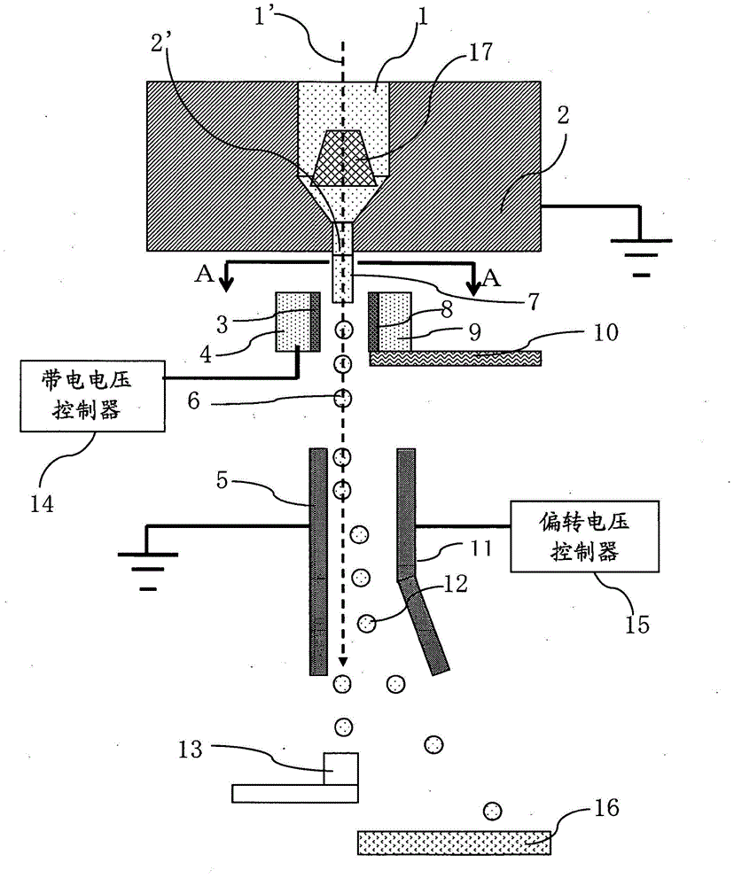
[0045] Embodiments of the present invention described below are applied to Figure 7 An example of the case of a continuous ejection type inkjet recording apparatus among the inkjet recording apparatuses shown.

[0046] use figure 1 , 2 , 3, and 4 describe the schematic structure of, in particular, the nozzles of the inkjet head in the continuous discharge type inkjet recording device (or continuous inkjet device) as the first embodiment of the present invention.

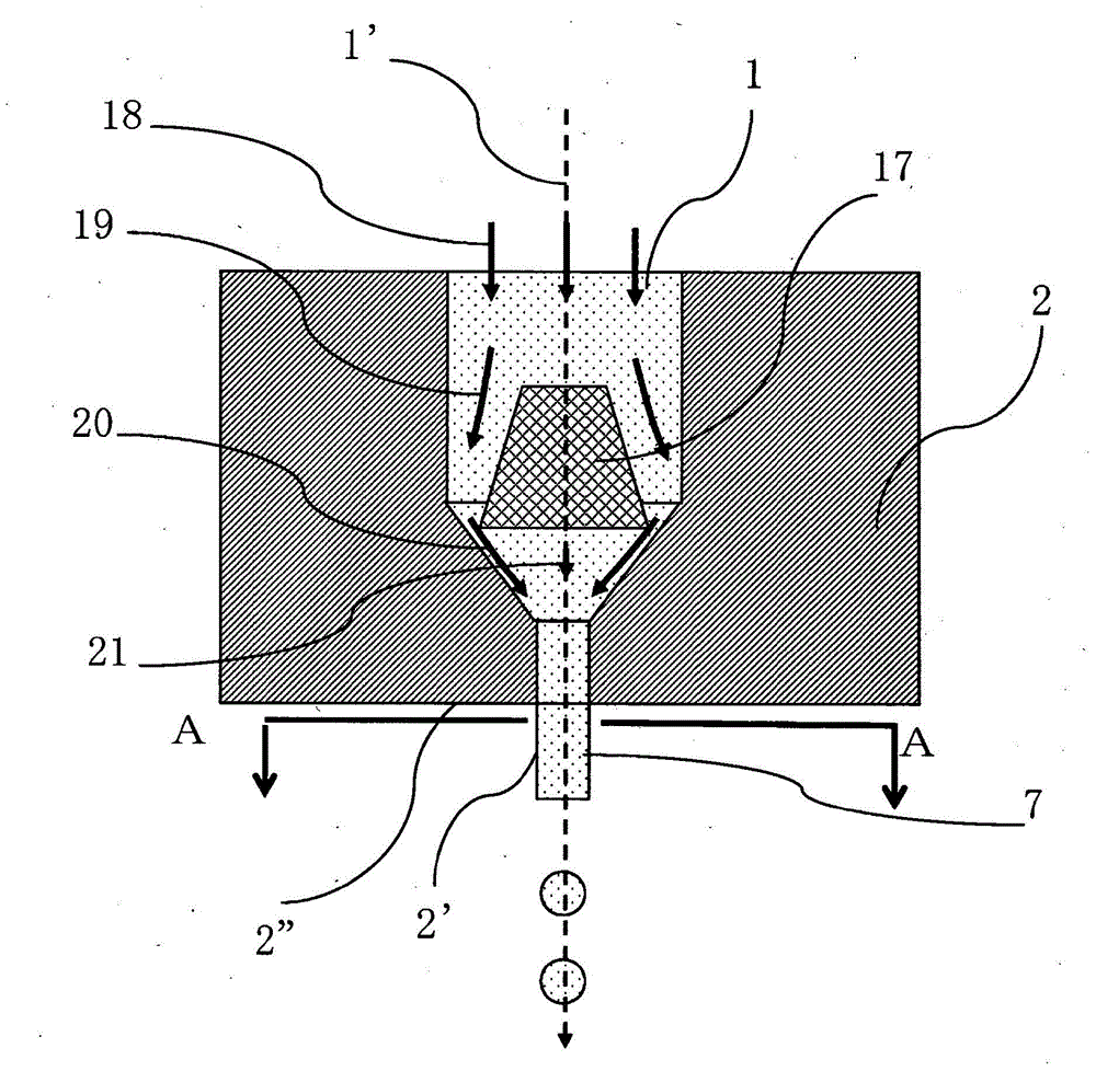
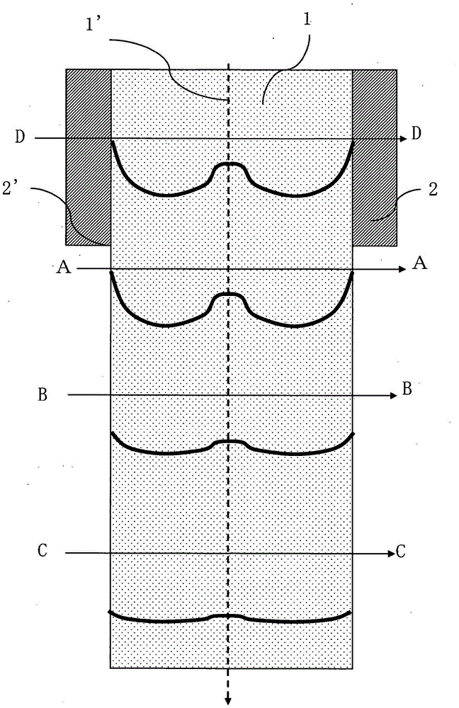
[0047] figure 1 is a structural diagram of main parts of the first embodiment of the present invention, showing Figure 7 A diagram of the internal structure of the inkjet head 32. figure 2 It is a structural diagram of the main part of the sprinkler head 2. image 3 is description figure 1 A detailed diagram of the variation of the velocity distribution of the ink near the AA section near the outlet of the ink chamber 1 in the traveling direction. Figure 4 It is a structural diagram of main parts of the fi...

no. 2 example

[0062] Next, a second embodiment of the present invention will be described.

[0063] Figure 5 It is a structural diagram of main parts of the second embodiment of the present invention. exist Figure 5 Other structures not shown in the figure 1 example of the same structure. exist Figure 5 Among them, the speed suppressing member 17 in the vicinity of the axis has a conical shape whose cross-sectional area becomes smaller along the traveling direction. With such a configuration, since the tip of the cone is brought closer to the nozzle outlet 2', a concave velocity distribution in which the velocity in the vicinity of the center axis can be further reduced can be generated, and there is an effect that the splitting distance can be shortened.

no. 3 example

[0065] Next, a third embodiment of the present invention will be described.

[0066] Figure 6 It is a structural diagram of main parts of the third embodiment of the present invention. exist Figure 6 Other structures not shown in the figure 1 example of the same structure. exist Figure 6 Among them, the speed suppressing member 17 in the vicinity of the axis has a double pipe structure that divides the flow of ink into the inner side and the outer side, and at the outlet, the inner side speed becomes slower than the outer side speed. This velocity distribution is obtained by making the cross-sectional area of ​​the outer side of the double pipe smaller than that of the inner side at the inlet and larger at the outlet.

[0067] With such a configuration, the velocity distribution can be controlled by selecting the inner and outer diameters of the double-layer tube, and therefore, there is an effect that the cutting distance can be easily designed in accordance with the ...


PUM


Abstract

An ink jet recording apparatus that can perform high velocity printing without printing distortion is realized. In a continuous discharge type ink jet recording apparatus, a unit that suppresses a velocity in the vicinity of a center axis is disposed in a unit that injects ink droplets in which because a velocity in an outer periphery is higher than that in a center of a discharged liquid column, a velocity on a surface of the liquid column becomes quickly high, and a capillary wave that propagates on a surface of the liquid column in a travel direction is quickly amplified because the velocity becomes quickly a velocity suitable for droplet breakup, the droplet breakup is quickly generated, and the droplet breakup is surely generated within a charging electrode located next to the nozzle. As a result, an ink jet recording apparatus stable in printing quality performance is provided.

Description

technical field [0001] The present invention relates to an inkjet recording device. Background technique [0002] Among the inkjet recording devices, the continuous discharge type inkjet device is a highly stable liquid droplet ejection with high reliability and high maintainability compared with the drop-on-demand type inkjet device used in home or office printers. device. [0003] Therefore, the continuous ejection type inkjet recording device can also be applied to manufacturing devices such as electronic equipment that require functional ink coating and pattern formation using liquids that require high reliability, high maintenance, and high stability. In addition, this device can also be used as a three-dimensional model, such as a 3D printer. [0004] In the continuous ejection type inkjet recording device, the liquid (ink) stored in the ink cartridge is pressurized by a pump or the like, and is continuously ejected from minute nozzles. On the other hand, the piezoe...

Claims


Application Information

Patent Timeline
Patent Type & Authority Applications(China)
IPC IPC(8): B41J2/07
CPCB41J2/02B41J2002/14475
Inventor 池川正人石井英二原田信浩宫尾明
Owner HITACHI IND EQUIP SYST CO LTD
Why Eureka
Try Eureka