Image Forming Apparatus

a technology of forming apparatus and forming chamber, which is applied in the direction of optics, instruments, electrographic processes, etc., can solve the problems of increasing the chance of toner melting, poor print quality, and inability to produce high-quality images, so as to improve the print quality and high speed

Active Publication Date: 2007-03-29
OKI ELECTRIC IND CO LTD
View PDF11 Cites 19 Cited by
  • Summary
  • Abstract
  • Description
  • Claims
  • Application Information

AI Technical Summary

Benefits of technology

[0010] An object of the present invention is to provide an image forming apparatus that improves the print quality and that is capable of printing at high speed.
[0011] Another object of the invention is to provide an image forming apparatus that prevents developer in the developing unit from melting.

Problems solved by technology

Thus, the toner in a developing unit may melt due to the heat from the fixing unit.
A toner for high speed printing has a low-melting point, and therefore increases the chance of the toner melting due to the heat from the fixing unit.
The result is a poor print quality.

Method used


Image

  • Image Forming Apparatus
  • Image Forming Apparatus
  • Image Forming Apparatus

Examples


first embodiment

[0038] Embodiments will be described in detail with reference to the accompanying drawings. An image forming apparatus will be described in terms of a printer.

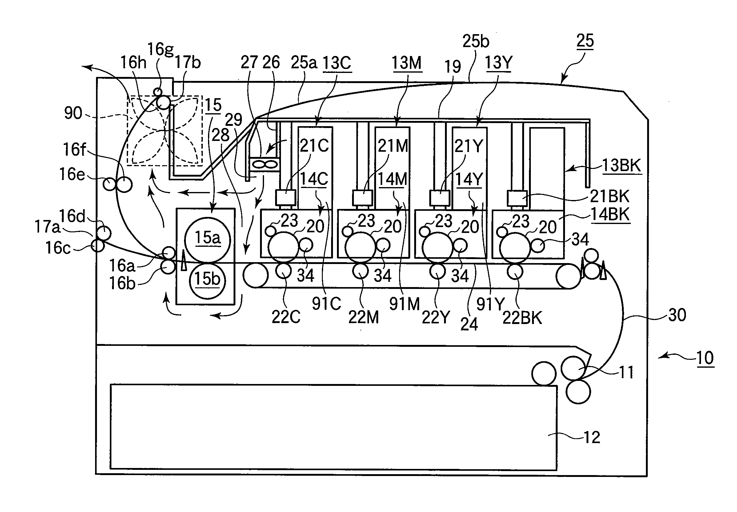
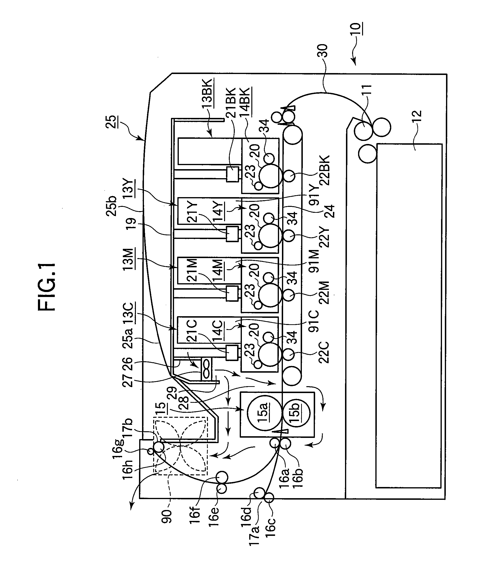
[0039]FIG. 1 is a cross sectional view illustrating the general configuration of a printer 10 of a first embodiment.

[0040] Referring to FIG. 1, a feed roller 11 is driven in rotation by a drive source, not shown, to feed paper from a paper cassette 12 into a transport path 30. The paper is advanced in the transport path 30 in a laterally centered position with respect to the transport path 30. As the transfer belt 24 runs, the paper passes through image forming sections 14BK (black), 14Y (yellow), 14M (magenta), and 14C (cyan) in sequence, advancing through transfer regions defined between the respective photoconductive drums 20 and transfer rollers 22Y, 22M, 22C, and 22BK.

[0041] The image forming sections 14Y, 14M, 14C, and 14BK each include a photoconductive drum 20, a charging roller 23, and a developing roller 34.

[0042...

second embodiment

[0059] Elements similar to those in the first embodiment have been given the same reference numerals and their description is omitted.

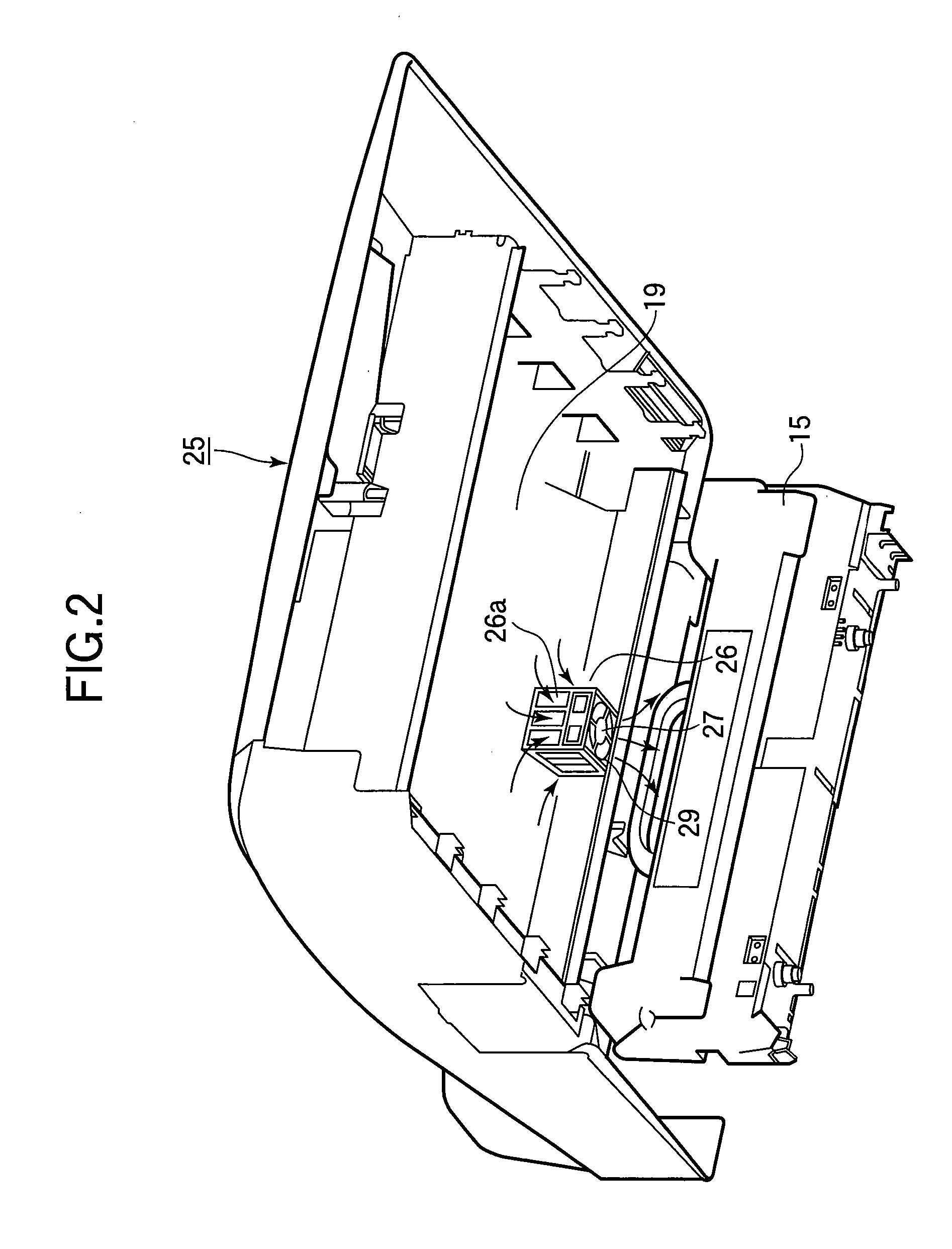
[0060]FIG. 3 illustrates the general configuration of a printer 10 of a second embodiment. FIG. 4 is a perspective view illustrating a pertinent portion of the printer 10.

[0061] A first path 28 is defined between the image forming section 14C and the fixing unit 15. A second path 32 is defined between an outer case 25 and a partition 19 that overlies toner reservoirs. An air chamber 31 defines a third path 31a between the first path 28 and the second path 32. The second path 32 and the third path 31a communicate with each other through openings 33 formed in the upper wall of the air chamber 31.

[0062] The air chamber 31 is located beside the toner reservoir 13C and substantially over the first path 28 defined between the image forming section 14C and the fixing unit 15.

[0063] The fan 27 rotates to suck in the relatively cool air into the air chambe...

third embodiment

[0065] Elements similar to those in the first and second embodiments have been given the same reference numerals and their description is omitted.

[0066]FIG. 5 illustrates the general configuration of a printer 10 of third embodiment. FIG. 6 is a perspective view illustrating a pertinent portion of the printer 10 with a partition 19 (FIG. 5) omitted for the sake of simplicity.

[0067] Referring to FIG. 5, a first path 28 is defined between the image forming section 14C and the fixing unit 15. A second path 32 is defined by an outer case 25, two opposing walls 45 (FIG. 6), and the partition 19 that overlies toner reservoirs 13BK, 13Y, 13M, and 13C. An air chamber 41 defines a third path 41a between the first path 28 and the second path 32. The air chamber 41 and the second path 32 communicate with each other through openings 43. As shown in FIG. 6, the air chamber 41 is in the shape of a rectangular box that longitudinally extends parallel to the fixing unit 15.

[0068] The second path...


PUM


Abstract

An image forming apparatus includes an image forming section that forms a toner image. A transferring section transfers the toner image formed onto a recording medium. A fixing unit is located adjacent the image forming section such that a first space is defined between the fixing unit and the image forming section. The fixing unit fixes the toner image on the recording medium. An air-chamber includes a wind exit and discharges the air through the wind exit such that the air flows into the first space. An air-propelling device propels the air to discharge through the wind exit.

Description

BACKGROUND OF THE INVENTION [0001] 1. Field of the Invention [0002] The present invention relates to an image forming apparatus. [0003] 2. Description of the Related Art [0004] A color printer is one of conventional image forming apparatuses such as printers, copying machines, facsimile machines and composite structure of these, i.e., multifunction printers (MFP). A color printer performs an electrophotographic image forming process. A charging roller charges the surface of a photoconductive drum. An LED head illuminates the charged surface of the photoconductive drum to form an electrostatic latent image. A thin layer of toner formed on a developing roller is deposited to the electrostatic latent image by the Coulomb force, thereby forming a toner image on the photoconductive drum. A transfer roller transfers the toner image onto paper. A cleaning unit removes the toner remaining on the photoconductive drum after transfer. [0005] The paper having the toner image on it advances to a...

Claims


Application Information

Patent Timeline
Patent Type & Authority Applications(United States)
IPC IPC(8): G03G21/20
CPCG03G21/206G03G2221/1645
Inventor YUASA, HIROSHI
Owner OKI ELECTRIC IND CO LTD
Why Eureka
Try Eureka