Ink cartridge and mount/demount mechanism for the same

a technology of ink cartridges and mounts, which is applied in printing and other directions, can solve the problems of etc., and achieves the effects of reducing increasing the ink flow amount, and increasing the size of the ink cartridg

Inactive Publication Date: 2015-06-30
RISO KAGAKU CORP
View PDF9 Cites 19 Cited by
  • Summary
  • Abstract
  • Description
  • Claims
  • Application Information

AI Technical Summary

Benefits of technology

[0019]However, the insertion shaft inserted into the ink supply port hinders the ink supply from the socket portion to the joint portion, and reduces the ink flow amount by an amount corresponding to the cross-sectional area of the insertion shaft. To compensate this, the ink flow amount may be increased by increasing the diameter of the ink supply port, but this leads to increase in the size of the ink cartridge.
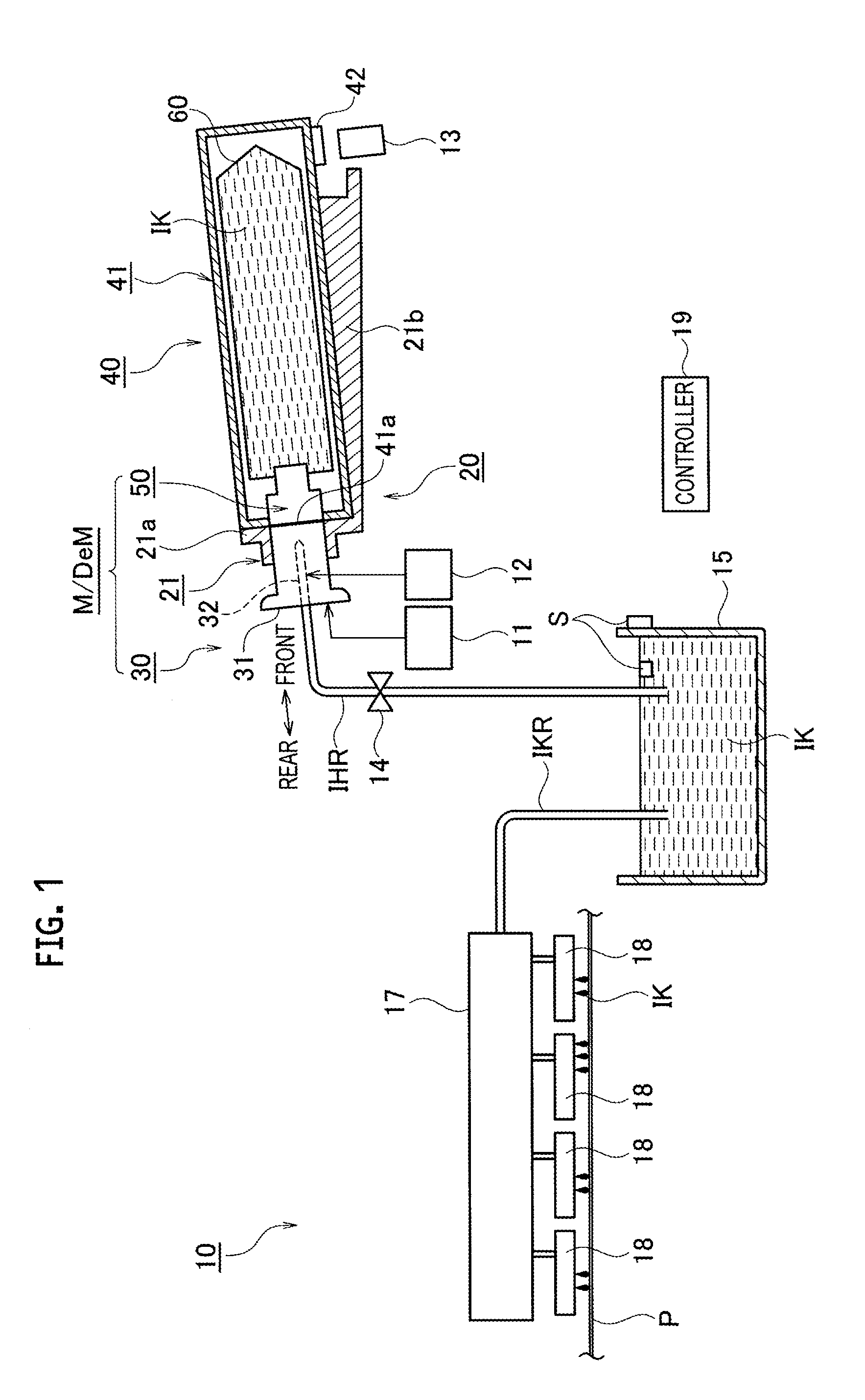
[0020]An object of the present invention is to provide an ink cartridge and an ink cartridge mount / demount mechanism in which an insertion shaft provided in a center portion of a joint body does not hinder an ink supply port of a socket body from supplying an ink from a socket portion in the ink cartridge to a joint portion in a printing machine.
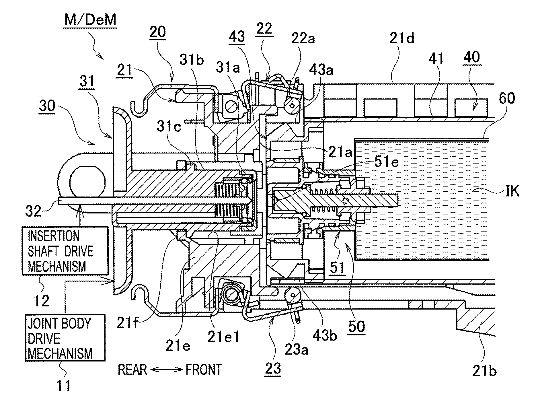
[0022]The configuration described above particularly includes the inside plug lock portion configured to lock the inside plug at the position where the inside plug is pressed by the insertion shaft at the pressing position in the joint portion, against the biasing force from the ink storage container side, when the socket portion in the ink cartridge and the joint portion in the printing machine are fitted to each other, and to maintain the locked state of the inside plug even if the insertion shaft retreats to the retreat position outside the ink supply port after the locking of the inside plug. Accordingly, the insertion shaft does not hinder the ink supply port from supplying the ink from the socket portion to the joint portion and a large amount of ink on the socket portion side can flow from the ink supply port into the joint portion. In this configuration, it is possible to reduce an ink supply time without increasing the size of the ink cartridge and to thereby print image information on many paper sheets at high speed in the printing machine.
[0024]In the configuration described above, particularly, before the ink cartridge is pulled out from the printing machine, the ink passage is sealed with the inside plug by moving the insertion shaft to the pressing position to unlock the inside plug, and then by moving the insertion shaft toward the retreat position. Accordingly, the ink on the socket portion side does not leak from the ink supply port and the amount of ink which may drip between the joint portion and the socket portion can be suppressed to the minimum. Hence, it is possible to suppress the dripping of the ink from the ink supply port which occurs when the fitting between the joint portion and the socket portion is released. The ink cartridge can be thus carried at ease after being detached from the printing machine.
[0026]In the configuration described above, in order to detachably fit the socket portion provided on the distal end side of the ink cartridge to the joint portion provided in the printing machine, the joint portion includes the joint body and the insertion shaft and the socket portion includes the socket body, the inside plug, and the inside plug lock portion. In this case, particularly, the inside plug lock portion locks the inside plug at the position where the inside plug is pressed by the insertion shaft at the pressing position in the joint portion and maintains the locked state of the inside plug even if the insertion shaft retreats to the retreat position outside ink supply port after the locking of the inside plug. As a result, the insertion shaft does not hinder the ink supply port from supplying the ink from the socket portion to the joint portion, and a large amount of ink on the socket body side can flow to the joint body side from the ink supply port. In this configuration, it is possible to reduce an ink supply time without increasing the sizes of the printing machine and the ink cartridge and to thereby print image information on many paper sheets at high speed in the printing machine.

Problems solved by technology

However, the insertion shaft inserted into the ink supply port hinders the ink supply from the socket portion to the joint portion, and reduces the ink flow amount by an amount corresponding to the cross-sectional area of the insertion shaft.
To compensate this, the ink flow amount may be increased by increasing the diameter of the ink supply port, but this leads to increase in the size of the ink cartridge.

Method used


Image

  • Ink cartridge and mount/demount mechanism for the same
  • Ink cartridge and mount/demount mechanism for the same
  • Ink cartridge and mount/demount mechanism for the same

Examples


Embodiment Construction

[0038]In the following detailed description, for purposes of explanation, numerous specific details are set forth in order to provide a thorough understanding of the disclosed embodiments. It will be apparent, however, that one or more embodiments may be practiced without these specific details. In other instances, well-known structures and devices are schematically shown in order to simplify the drawing.

[0039]Description will be hereinbelow provided for an embodiment of the present invention by referring to the drawings. It should be noted that the same or similar parts and components throughout the drawings will be denoted by the same or similar reference signs, and that descriptions for such parts and components will be omitted or simplified. In addition, it should be noted that the drawings are schematic and therefore different from the actual ones.

[0040]An ink cartridge and an ink cartridge mount / demount mechanism in an embodiment of the present invention are described below in...


PUM


Abstract

An ink cartridge includes: an ink storage container configured to store ink; a socket portion provided at one end of the ink storage container and configured to be fitted to and detached from a joint portion of a printing machine; an ink supply port provided in the socket portion; an inside plug configured to seal an ink passage to the ink supply port by using a biasing force coming from a direction of the ink storage container; and an inside plug lock portion configured to lock the inside plug at a position where the inside plug is pressed by an insertion shaft, and maintain a locked state of the inside plug independently of a retreating of the insertion shaft to a retreat position after a locking of the inside plug.

Description

CROSS REFERENCE TO RELATED APPLICATION[0001]This application is based upon and claims the benefit of priority from the prior Japanese Patent Application No. 2014-002093, filed on Jan. 9, 2014, the entire contents of which are incorporated herein by reference.BACKGROUND[0002]1. Technical Field[0003]The present invention relates to an ink cartridge and an ink cartridge mount / demount mechanism which are configured such that a socket portion provided in the ink cartridge is detachably fitted to a joint portion provided in a printing machine.[0004]2. Related Art[0005]Generally, an inkjet printing machine employing an inkjet method uses multiple ink cartridges respectively storing inks of colors such for example as yellow (Y), magenta (M), cyan (C), and black (K).[0006]A socket portion provided in each of the ink cartridges is detachably fitted to a joint portion provided in the inkjet printing machine and the ink in the ink cartridge is thereby supplied from the socket portion to the ink...

Claims


Application Information

Patent Timeline
Patent Type & Authority Patents(United States)
IPC IPC(8): B41J2/175
CPCB41J2/17523B41J2/175B41J2/17513B41J2/1752B41J2/17553
Inventor TOMINAGA, HIROTAKASHIMAMURA, NORIHISA
Owner RISO KAGAKU CORP
Why Eureka
Try Eureka