

Conveyor device and inkjet recording apparatus
A technology of conveying device and conveyor belt, which is applied in the directions of printing device, transportation and packaging, printing, etc., and can solve the problems of flying, complicated structure of inkjet recording device, and separation from paper, etc.
- Summary
- Abstract
- Description
- Claims
- Application Information
AI Technical Summary
Problems solved by technology
Method used
Image

Examples
no. 1 approach
[0024] (First embodiment: basic principle)
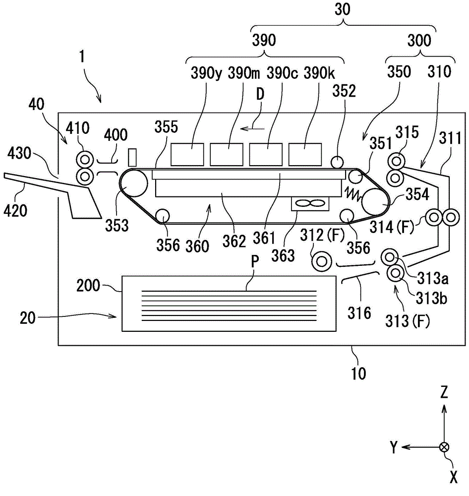
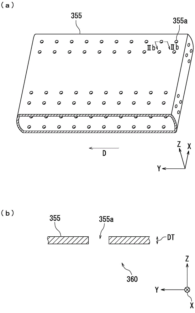
[0025] refer to figure 1 and figure 2 (a) The basic principle of the transport device according to the first embodiment of the present invention will be described. figure 1 A schematic configuration of the inkjet recording device 1 is shown. figure 2 (a) is a perspective view showing the conveyor belt 355 .
[0026] The inkjet recording device 1 includes a transport device 300 and a recording head 390 . The conveying device 300 is arranged opposite to the recording head 390 .
[0027] The transport device 300 includes a transport belt 355 and a suction unit 360 . The conveyance belt 355 conveys the recording medium P. As shown in FIG. The suction unit 360 sucks the recording medium P through the conveyor belt 355 . The suction part 360 includes a guide member 361 . The guide member 361 supports the recording medium P via the conveyor belt 355 .
[0028] [Structure of Inkjet Recording Apparatus 1 ]
[0029] refer to figu...
no. 2 approach
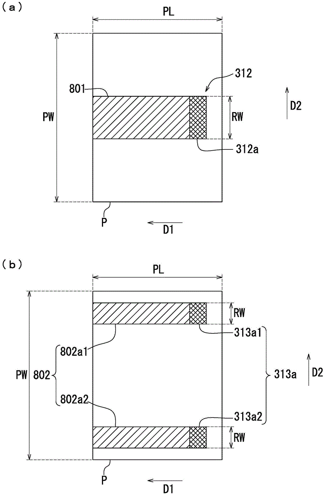
[0079] Next, refer to Figure 6 , Figure 7 (a) and Figure 7 (b) The conveyor belt 355 which concerns on 2nd Embodiment of this invention is demonstrated. Figure 6 , Figure 7 (a) and Figure 7 (b) is a top view which shows the conveyor belt 355 which concerns on 2nd Embodiment of this invention.
[0080] Figure 6 It shows the conveyance belt 355 when the paper feed roller 312 is in contact with a part of the recording medium P. As shown in FIG. Figure 7 (a) shows the conveyance belt 355 when the paper feed roller 312 and the supply roller 313 a (two roller members) are in contact with a part of the recording medium P. FIG. Figure 7 (b) shows the conveyance belt 355 when the paper feed roller 312 and the supply roller 313a (four roller members) are in contact with a part of the recording medium P. As shown in FIG.
[0081] first of all, yes Figure 6 , Figure 7 (a) and Figure 7 The conveyor belt 355 shown in (b) is demonstrated. Figure 6 The conveyor belt 35...
no. 3 approach
[0086] Next, refer to Figure 8 , Figure 9 (a) and Figure 9 (b) The conveyor belt 355 which concerns on 3rd Embodiment of this invention is demonstrated. Figure 8 , Figure 9 (a) and Figure 9 (b) is a top view which shows the conveyor belt 355 which concerns on 3rd Embodiment of this invention.
[0087] Figure 8 It shows the conveyance belt 355 when the paper feed roller 312 is in contact with a part of the recording medium P. As shown in FIG. Figure 9 (a) shows the conveyance belt 355 when the paper feed roller 312 and the supply roller 313 a (two roller members) are in contact with a part of the recording medium P. FIG. Figure 9 (b) shows the conveyance belt 355 when the paper feed roller 312 and the supply roller 313a (four roller members) are in contact with a part of the recording medium P. As shown in FIG.
[0088] Figure 8 , Figure 9 (a) and Figure 9 The regions on the conveyer belt 355 shown in (b) are respectively with reference to Figure 6 , F...
PUM
 Abstract
Description
Claims
Application Information