
Handle module

A handle and base technology, which is applied in the direction of leaf handles, door/window accessories, connecting components, etc., can solve the problem that the handle module 50 and the cover plate 60 cannot have an actuating stroke, and achieve the effect of saving configuration space

Active Publication Date: 2015-11-25
WISTRON CORP +1
View PDF3 Cites 10 Cited by
  • Summary
  • Abstract
  • Description
  • Claims
  • Application Information

AI Technical Summary

Problems solved by technology

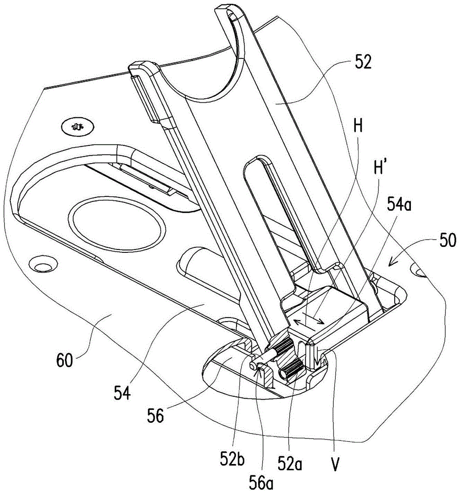
Under the above-mentioned configuration and actuation mode of the known handle module 50, the pin shaft 52a not only produces displacement in the horizontal direction H, but also produces a displacement in the vertical direction V during the actuation process, so the main body of the chassis must accommodate the movement of the pin shaft 52a. The chute 54a, thus sacrificing part of the configuration space in the main body of the chassis
In addition, in order not to make the chute 54a occupy too much space in the main body of the chassis, the length of the chute 54a along the vertical direction V is limited, so that the handle module 50 and the cover plate 60 cannot have a large actuation stroke in the horizontal direction H.

Method used


Image

  • Handle module
  • Handle module
  • Handle module

Examples


Embodiment Construction

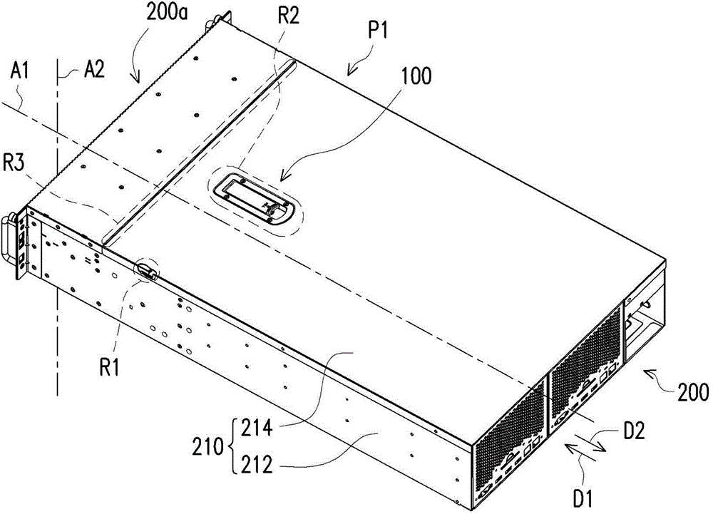
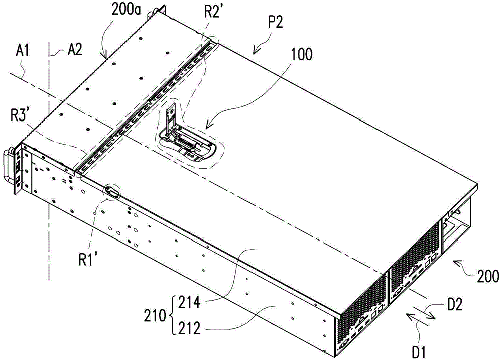
[0064] figure 2 It is a perspective view of a handle module applied to a server according to an embodiment of the present invention. image 3 draw figure 2 The handle module drives the cover to move. Please refer to figure 2 and image 3 , the handle module 100 of this embodiment is applied to the chassis 210 of the server 200 , the chassis 210 includes a main body 212 and a cover 214 , and the cover 214 is used to cover the components disposed in the main body 212 . The handle module 100 is mounted on the cover plate 214 and used to drive the cover plate 214 from figure 2 The first position P1 shown moves along the first axis A1 to image 3 The second position P2 shown is to release the fastening relationship between the cover plate 214 and the main body 212 so that the cover plate 214 can be opened. In other embodiments, the handle module 100 can be applied to casings of other types of devices, and the present invention is not limited thereto.

[0065] Figure 4 ...


PUM


Abstract

A handle module adapted to a chassis is provided. The chassis includes a main body and a cover. The handle module includes a base, a handle, a sliding component and a linking rod. The base is disposed on the cover. The handle is pivoted to the base. The sliding component is connected to the main body and is slidably disposed on the base. Two ends of the linking rod are pivoted to the handle and the sliding component respectively. When the handle closed to the base is rotated relative to the base to be expanded from the base, the handle pulls the sliding component to slide relative to the base along a first axis by the linking rod, so as to drive the cover to move from a first position to a second position relative to the main body along the first axis.

Description

technical field [0001] The invention relates to a handle module, and in particular to a handle module suitable for a cabinet. Background technique [0002] The server (server) is the core computer that serves each computer or portable electronic device in the network system. It can provide functions such as disk and printing services required by network users, and also allows each client to share various resources in the network environment with each other. The basic architecture of a server is roughly the same as that of a general personal computer, consisting of a central processing unit (CPU), a memory (Memory), and an input / output (I / O) device. Generally, the cover plate is used to cover the components in the server case, and the cover plate is mostly designed to move relative to the main body of the case by means of push-pull handles, etc., to release the fastening relationship between the cover plate and the main body of the case, so that The cover can be opened. [...

Claims


Application Information

Patent Timeline
IPC IPC(8): E05B5/00
CPCE05B5/00E05B5/003Y10T292/57
Inventor 毛忠辉杜山根邹志鹏
Owner WISTRON CORP
Learn More