Stator for rotating machine, holder for use with stator, rotating machine, and automobile

A technology for a rotating electrical machine and a retainer, applied in the automotive field, can solve problems such as difficulty in miniaturization and increased configuration space

Inactive Publication Date: 2013-05-08
KK TOSHIBA +1
View PDF6 Cites 8 Cited by
  • Summary
  • Abstract
  • Description
  • Claims
  • Application Information

AI Technical Summary

Problems solved by technology

However, this rotating electric machine has four slip rings, and even if the slip rings are arranged concentrically with respec...

Method used


Image

  • Stator for rotating machine, holder for use with stator, rotating machine, and automobile
  • Stator for rotating machine, holder for use with stator, rotating machine, and automobile
  • Stator for rotating machine, holder for use with stator, rotating machine, and automobile

Examples


Embodiment Construction

[0016] Below, refer to Figure 1 to Figure 7 , an embodiment applied to a drive motor used in an electric vehicle and driven by an inverter will be described. in addition, Figure 7 An electric vehicle equipped with the driving motor 1 as a rotating electrical machine is shown.

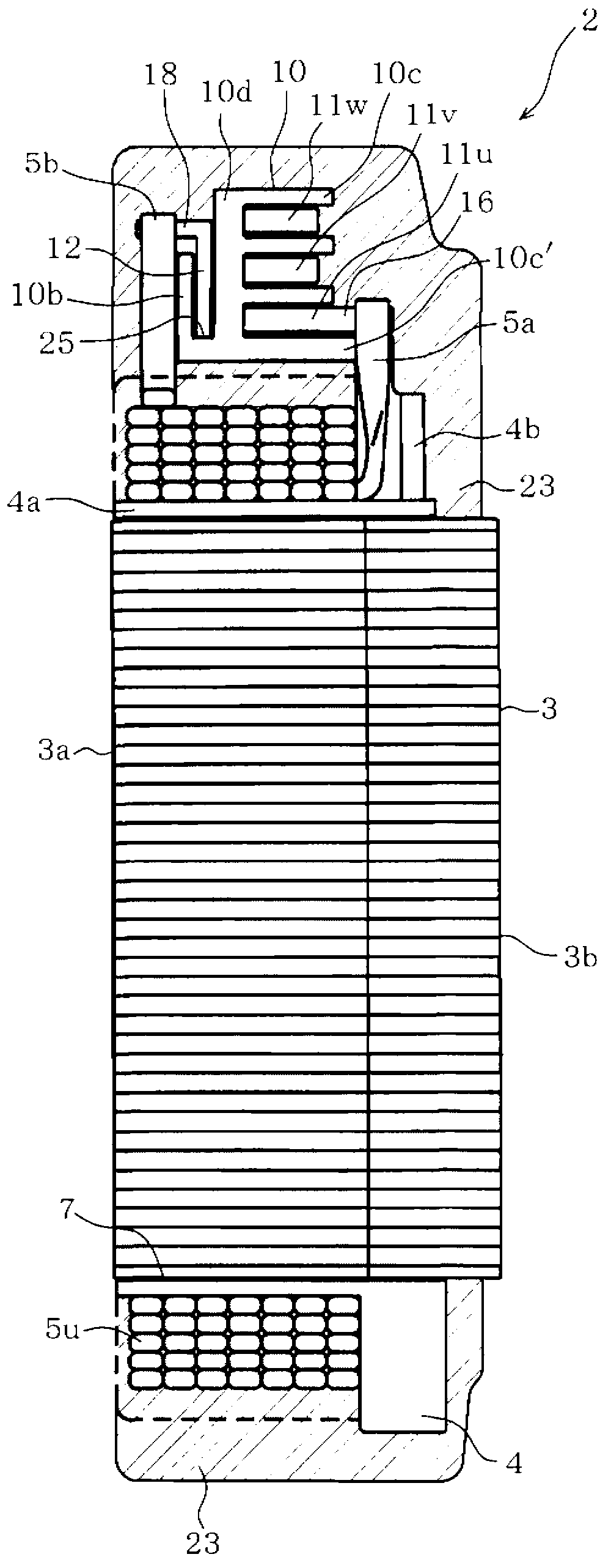
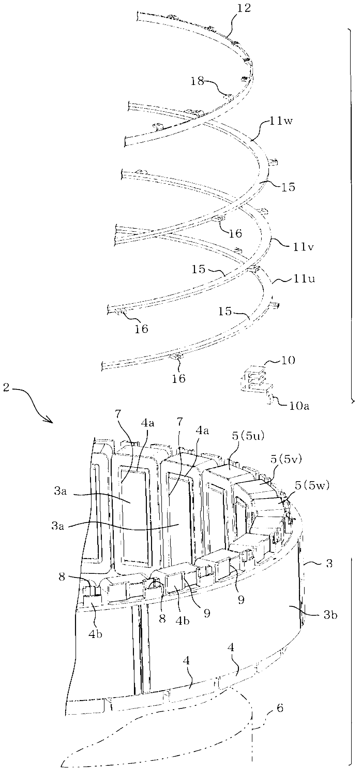
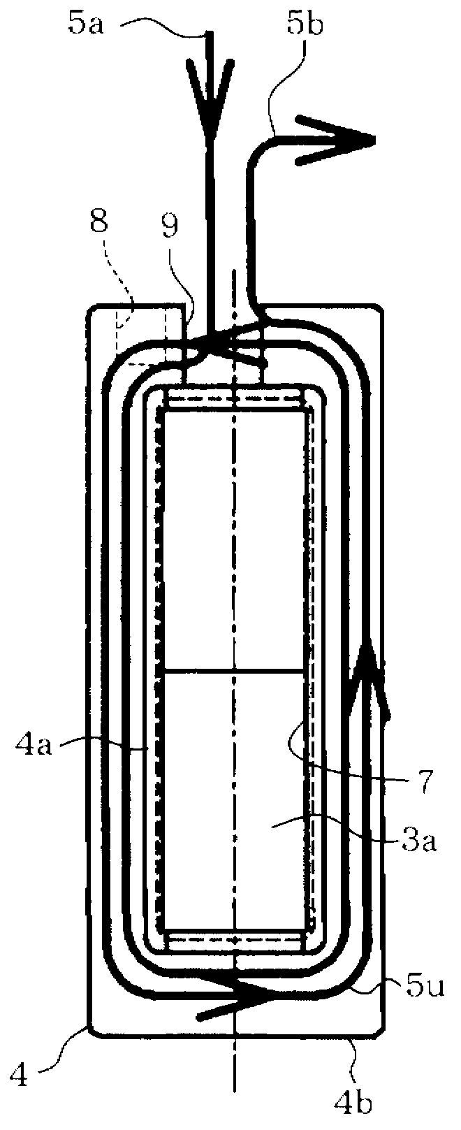
[0017] Such as figure 2 As shown, the stator 2 of the drive motor 1 includes a substantially cylindrical stator core 3 formed by laminating a large number of annularly configured electromagnetic steel sheets. The stator core 3 has: a cylindrical yoke 3b; and a plurality of (for example, 24) teeth 3a provided at equal intervals in the circumferential direction on the inner peripheral portion of the yoke 3b. Each tooth 3a is configured in a square column shape, and is formed so as to protrude from the inner peripheral surface of the yoke 3b in the center direction. Three-phase (U-phase, V-phase, and W-phase) windings 5 ​​(U-phase winding 5 u , V-phase winding 5 v , and W-phase winding 5 w ) are wou...


PUM


Abstract

A stator(2) of a rotating machine(1) includes a stator core (3), a plurality of winding wires wound on the stator core (3), a first bus ring(11u, 11v, 11w), a second bus ring(12), and a holder device. The first bus ring(11u, 11v, 11w) has a first radial dimension and selectively connects electrically with each of the wires. The second bus ring(12) has a second radial dimension different from the first radial dimension and selectively connects electrically with each of the wires. The holder device holds the first bus rings (11u, 11v, 11w) and the second bus ring (12). The holder device includes a first and a second support portion. The first support portion supports the first bus rings (11u, 11v, 11w) aligned along an axial direction of the stator core(3). The second support portion supports the second bus ring (12) on a radially outward or inward side of the first bus rings(11u, 11v, 11w).

Description

technical field [0001] Embodiments of the present invention relate to a stator of a rotating electrical machine, a holder for the stator, a rotating electrical machine including the stator, and an automobile including the rotating electrical machine. Background technique [0002] Conventionally, in a vehicle rotating electrical machine mounted in an electric vehicle or a hybrid vehicle as a drive motor, three-phase windings wound around a stator core are connected for each phase via bus rings. In this case, each winding uses a U-phase slip ring, a V-phase slip ring, a W-phase slip ring, and a neutral point slip ring to form a star connection. [0003] Here, the above-mentioned rotary electric machine for a vehicle is required to be miniaturized. However, this rotating electric machine includes four slip rings, and even if the slip rings are arranged concentrically with respect to the stator, the arrangement space increases in the radial direction of the stator, making it di...

Claims


Application Information

Patent Timeline
IPC IPC(8): H02K1/12H02K13/02H02K3/34H02K5/14
CPCH02K3/522Y02T10/641H02K3/52H02K2203/09Y02T10/7005B60L2220/50B60L50/51B60L58/21Y02T10/64Y02T10/70H02K7/006
Inventor 金田数马伊藤涉加藤裕典
Owner KK TOSHIBA
Why Eureka
Try Eureka