Carrier system for a medical apparatus

a technology for supporting systems and medical devices, applied in the direction of medical lighting, building scaffolds, domestic objects, etc., can solve the problems of preventing infection, cables, recesses and projections on the support system, and can only be cleaned with difficulty, so as to achieve good maneuverability of medical-optical equipmen

Inactive Publication Date: 2005-05-26
CARL ZEISS STIFTUNG
View PDF16 Cites 7 Cited by
  • Summary
  • Abstract
  • Description
  • Claims
  • Application Information

AI Technical Summary

Benefits of technology

[0022] In a further embodiment of the invention, the tube-shaped holding member is connected to the carrier arm by a rotation joint. In this way, good maneuverability for medical-optical equipment is ensured which is accommodated on the carrier system.
[0023] In another embodiment of the invention, at least one joint unit is configured as a rotation joint having a cable passthrough. In this way, a covered cable passthrough through the entire carrier system is made possible.
[0024] According to still another feature of the invention, the means “compensation of a load torque” are configured as spring means. In this way, a force-free movement for medical-optical equipment is possible.
[0025] According to another feature of the invention, the spring means include a torsion spring. In this way, a space-saving configuration is made possible for a unit for compensation of a load torque.
[0026] In another embodiment of the invention, the spring means include a linear spring. In this way, a state of equilibrium can be precisely adjusted in a unit for rotational decoupling.
[0027] According to another feature of the invention, the carrier system includes at least one magnetic brake. In this way, a user-friendly locking of the carrier system is made possible.

Problems solved by technology

Surgical microscopes utilized to carry out surgical procedures can hold the danger of a source of infection.
Freely guided cables, recesses and projections on a support system can, however, be cleaned only with difficulty.

Method used


Image

  • Carrier system for a medical apparatus
  • Carrier system for a medical apparatus
  • Carrier system for a medical apparatus

Examples


Embodiment Construction

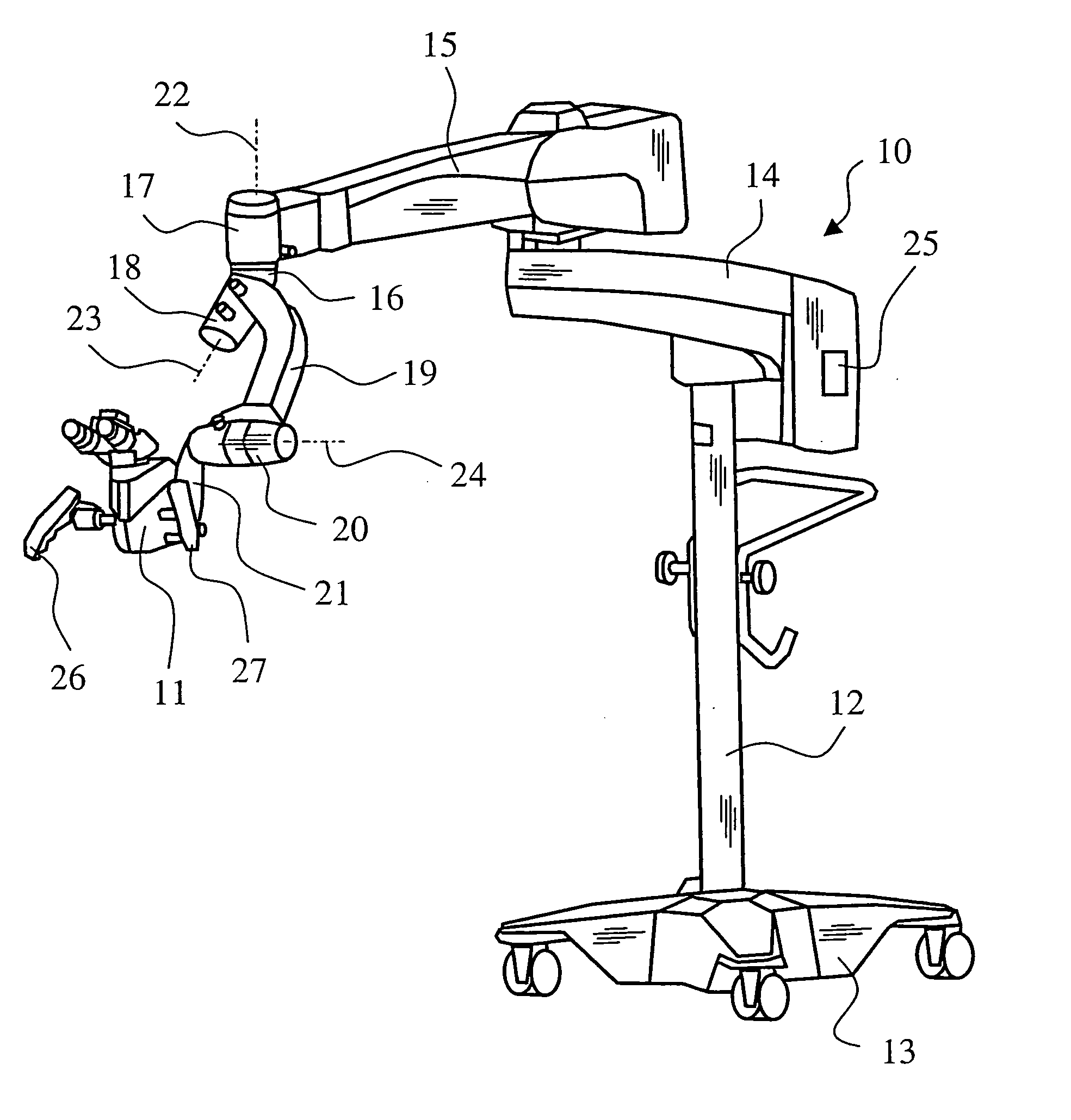
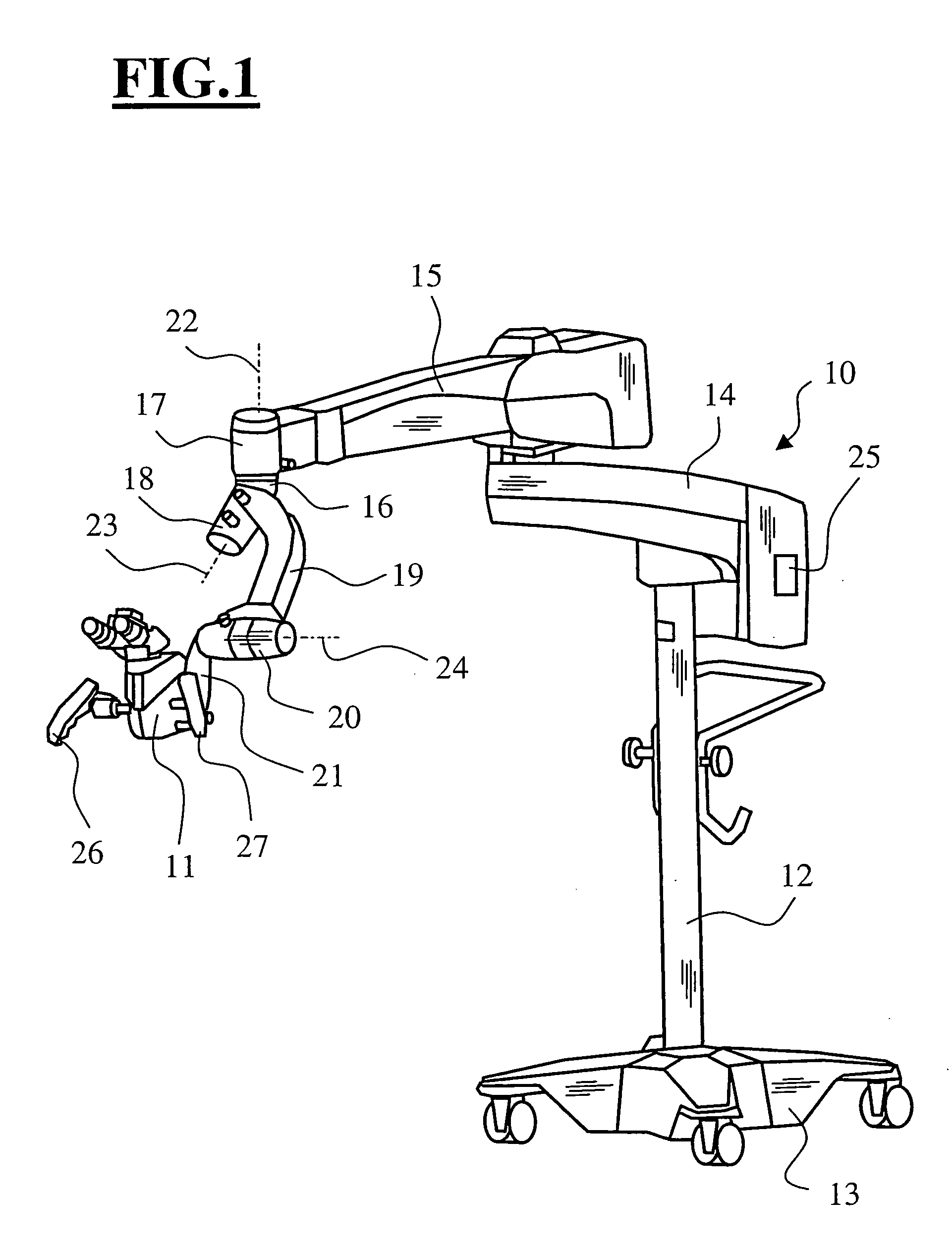
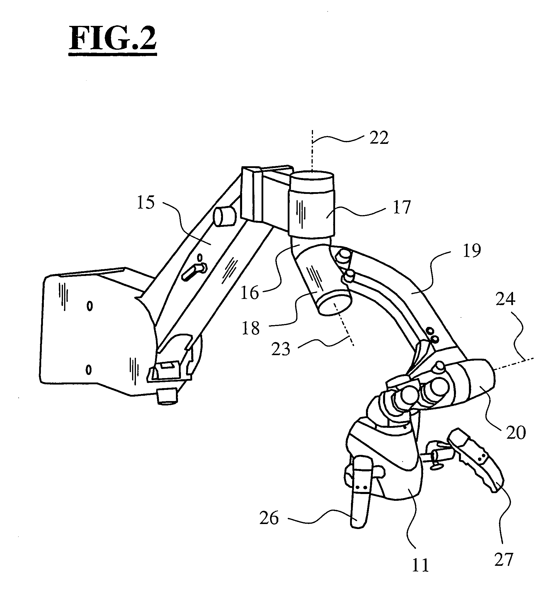
[0041]FIG. 1 shows a carrier system 10 for a medical apparatus on which a surgical microscope 11 is accommodated. The carrier system 10 is configured as a stand unit 10 and the stand unit includes a stand column 12 which is held by a movable base 13. A first carrier arm 14 is accommodated on the stand column 12 so as to be rotationally movable. This first carrier arm 14 carries a second carrier arm 15 on which a carrier member 16 is journalled in a rotation joint 17. The surgical microscope 11 with a first holding arm 19 is accommodated on the carrier member 16 via a joint unit 18 configured as a rotation joint. The holding arm 19 is connected to a second holding arm 21 via a joint unit 20 configured as a rotation joint. The second holding arm 21 functions as a connecting arm for taking up the surgical microscope 11.

[0042] The rotation joint 17 makes possible a rotational movement of the surgical microscope 11 about an axis 22 which is at an angle to a rotational axis of the rotati...


PUM


Abstract

A carrier system (10) for a medical apparatus (11) is disclosed. The carrier system includes rotation joints (17, 18, 20). A supply line harness runs in the carrier system (10) and is run so that it is covered. The rotation joint (18) includes a tube-shaped holding member on which fingers are formed which hold a rotation joint. A joint element, which is rotatably journalled in a joint receptacle, is provided in the rotation joint (20). The joint element has a wave-shaped section which is connected via a connecting section to an annularly-shaped section functioning to accommodate a connecting arm.

Description

BACKGROUND OF THE INVENTION [0001] A support system for a medical apparatus is, for example, manufactured by Carl Zeiss of Oberkochen, Germany, under the product designation “NC-4-Floor Stand” and “NC-4-Ceiling System”. Corresponding support systems are also offered by the Leica Company under the product designation “OHS-1 Floor Stand”. The Altvic Italia Company likewise offers such support systems for sale. These support systems have several linkage arms which, for example, support a surgical microscope. Wiring harnesses are mounted on these linkages which supply the surgical microscope with electrical energy and make possible the transmission of data with a video system. Also, these wiring harnesses can be in the form of light conductors and make available illuminating light for illuminating regions to be viewed. [0002] German patent publication 2,643,780 discloses a tiltable floor lamp which includes a ball joint having a cable passthrough in the lamp base. A telescope tube arran...

Claims


Application Information

Patent Timeline
Patent Type & Authority Applications(United States)
IPC IPC(8): A61B19/00F16M11/06G02B21/00G02B21/24
CPCA61B19/26A61B19/5223A61B2019/263F16M11/06F16M11/10F21W2131/20F16M11/42G02B21/0012G02B21/24F21L14/04F21V21/06F16M11/2071A61B2090/5025A61B90/50A61B90/20A61B90/25
Inventor STRAUSS, WOLFGANGKRUG, FRANZZIMMERMANN, FRITZABELE, ALFONSLEHMANN, MARENWEBER, LAURIC
Owner CARL ZEISS STIFTUNG
Why Eureka
Try Eureka