A solenoid valve structure of a camshaft timing angle adjustment device

A technology of angle adjustment device and solenoid valve, which is applied in the direction of valve device, control valve, function valve type, etc., can solve the problems that it takes time to establish the internal oil pressure of related parts, abnormal wear and tear of parts, cold start, insufficient oil pressure, etc., to achieve Effects of eliminating abnormal wear, improving response speed, and increasing service life

Active Publication Date: 2017-12-29
JAPHL POWERTRAIN SYST
View PDF8 Cites 0 Cited by
  • Summary
  • Abstract
  • Description
  • Claims
  • Application Information

AI Technical Summary

Problems solved by technology

The disadvantage of the electromagnetic proportional valve in the prior art is that when the engine is shut down, the hydraulic oil in the phaser of the engine camshaft timing angle adjustment device and the electromagnetic hydraulic valve will be unloaded again through the inlet P port, resulting in time needed for cold start again Establish the internal oil pressure of related parts. In this process, due to the insufficient internal oil pressure of the phaser of the camshaft timing angle adjustment device and the electromagnetic hydraulic valve, it will cause dry friction of the parts, resulting in abnormal wear of the parts and abnormal noise during cold start.

Method used


Image

  • A solenoid valve structure of a camshaft timing angle adjustment device
  • A solenoid valve structure of a camshaft timing angle adjustment device
  • A solenoid valve structure of a camshaft timing angle adjustment device

Examples


Embodiment Construction

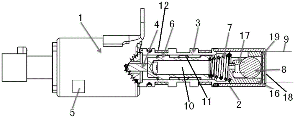
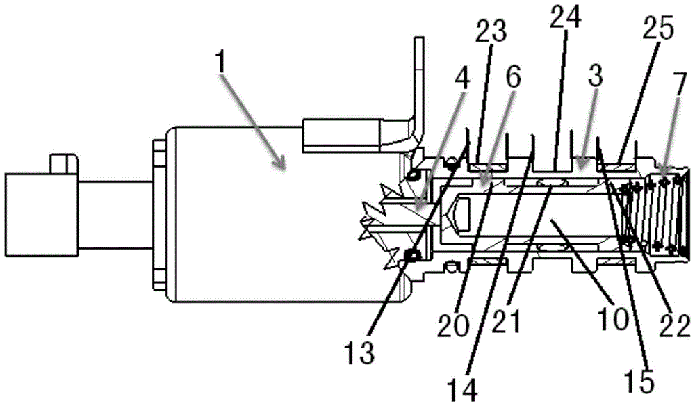
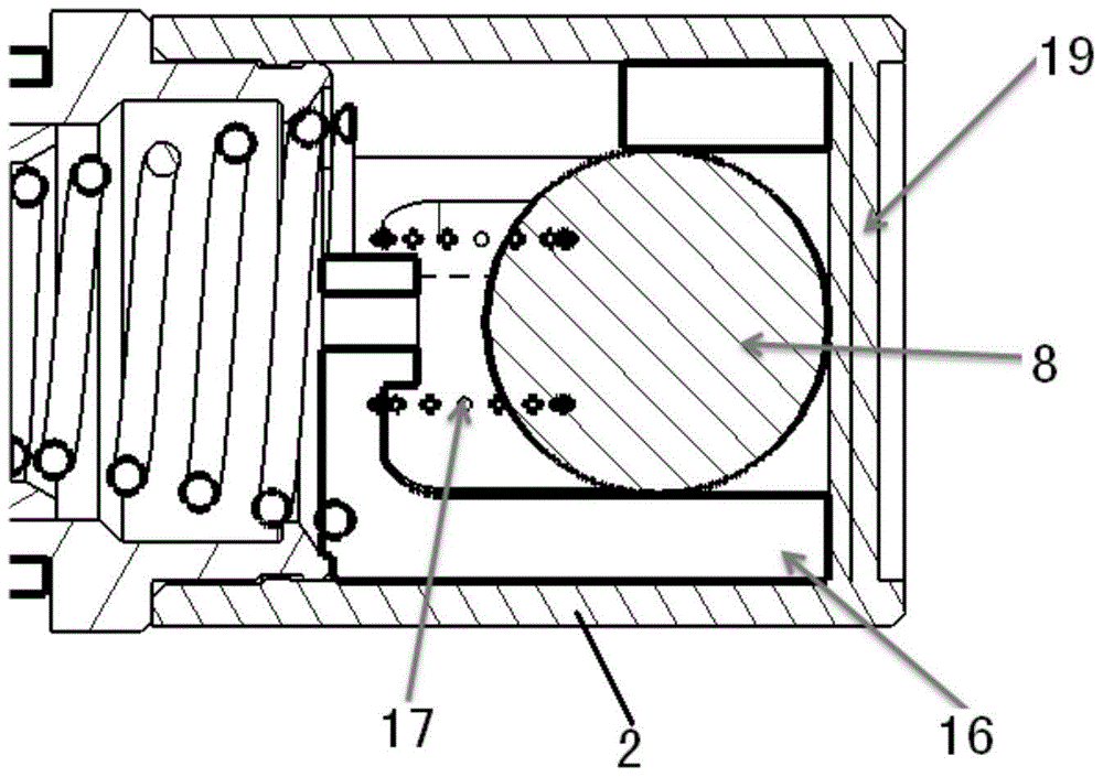
[0022] Below with reference to the accompanying drawings, through the description of the embodiments, the specific embodiments of the present invention, such as the shape, structure, mutual position and connection relationship between the various parts, the role and working principle of the various parts, etc., will be further described. Detailed instructions:

[0023] as attached figure 1 — attached image 3 As shown, the present invention is a solenoid valve structure of a camshaft timing angle adjustment device, including a solenoid valve body 1, and the solenoid valve body 1 includes a hollow valve sleeve 3, and a magnetic core shaft 4 is installed in the valve sleeve 3 One end of the magnetic core shaft 4 is connected to the control part 5 that controls the telescopic movement of the magnetic core shaft 4, the solenoid valve body 1 is connected to the check valve body 2, and the other end of the magnetic core shaft 4 is connected to the valve core 6, the valve The core ...


PUM


Abstract

The invention provides a solenoid valve structure of a camshaft timing angle adjustment device applied in the field of valve timing components, one end of a magnetic core shaft (4) in a valve sleeve (3) of a solenoid valve body (1) of the solenoid valve structure It is connected with the control part (5), the solenoid valve body (1) is connected with the one-way valve body (2), the other end of the magnetic core shaft (4) is connected with the spool (6), and the spool (6) is connected with the compression spring (7) connection, the compression spring (7) is tightly connected with the inner wall of the valve sleeve (3), the pressure spring (17) and the ball (8) are installed in the check valve body (2), and one end of the pressure spring (17) is connected with the plastic The skeleton (16) is connected, the other end of the pressure spring (17) is connected with the sphere (8), one end of the check valve body (2) is connected with the solenoid valve body (1), and the other end of the check valve body (2) is connected with the solenoid valve body (1). The oil supply pipeline (9) is connected, and the structure of the present invention eliminates the problems of abnormal wear inside the electromagnetic valve structure and abnormal noise at cold start, and improves the response speed of the phaser.

Description

technical field [0001] The invention belongs to the technical field of engine valve timing components, and more specifically relates to a solenoid valve structure of a camshaft timing angle adjustment device. Background technique [0002] The electromagnetic proportional valve in the prior art is used to control the internal combustion engine crankshaft to adjust the adjustment device of the camshaft rotation angle. It mainly consists of a hollow cylindrical electromagnet with an axially moving armature inside and a cylindrical valve body with an axial hole. and a piston valve arranged in the hole. The piston valve constituted as a hollow piston is effectively connected with the armature of the electromagnet through the push rod so that when the electromagnet flows around, the magnetic force of the axially moving armature is transmitted to the piston valve, and the piston valve is connected to the through-hole of the valve body. The force of the counter pressure spring move...

Claims


Application Information

Patent Timeline
Patent Type & Authority Patents(China)
IPC IPC(8): F16K15/18F01L1/344
CPCF01L1/3442F16K15/1823
Inventor 胡俊军范礼李雪涛张国立甄子源邵璠
Owner JAPHL POWERTRAIN SYST
Why Eureka
Try Eureka