
Intelligent emergency illumination and evacuation indication system

An emergency lighting and evacuation indicator light technology, applied in the direction of electrical transmission signal system, signal system components, instruments, etc., can solve the problems of staying, unable to meet the needs, unable to guide escape in time, to achieve rapid evacuation and reduce casualties Effect

Inactive Publication Date: 2015-11-25
蚌埠依爱消防电子有限责任公司
View PDF6 Cites 23 Cited by
  • Summary
  • Abstract
  • Description
  • Claims
  • Application Information

AI Technical Summary

Problems solved by technology

[0002] Modern buildings tend to be more and more high-rise, large-scale and complex. In such buildings, emergency response to fires is becoming more and more important. Systems that only perform fire detection and automatic alarms are far from being able to meet needs
At present, most of the escape instructions in the building are still on the independent emergency evacuation sign lights, which cannot guide the escape in time. Therefore, how to start the emergency evacuation plan according to the on-site fire alarm information when there are personnel on duty in the fire control room, or In the case of unattended, according to the situation of the fire scene, the evacuation route is automatically dynamically generated on the building plan, and the evacuation indicator light is activated to indicate the escape direction, which is a research direction of various fire alarm system manufacturers at present.

Method used


Image

  • Intelligent emergency illumination and evacuation indication system
  • Intelligent emergency illumination and evacuation indication system
  • Intelligent emergency illumination and evacuation indication system

Examples


Embodiment Construction

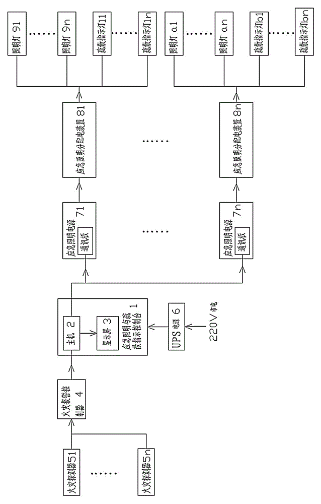
[0014] like figure 1 As shown, the present invention provides an intelligent emergency lighting and evacuation indication system, including an emergency lighting and evacuation indication console 1 composed of a host 2 connected to a display screen 3, the input interface of the host 2 is connected to a fire alarm controller 4, which can be adopted The ARCNET / CAN bus is connected; the fire alarm controller 4 is connected to a group of fire detectors 51~5n distributed in the building, and the output interface of the host computer 2 is connected to the emergency lighting power supply 71~7n equipped with a communication board. The lighting power supply is respectively connected to the corresponding emergency lighting distribution device 81~8n, the emergency lighting distribution device 81 is connected to the lighting lamp 91~9n, and the evacuation indicator light 11~1n, similarly, each emergency lighting distribution device A group of lighting lamps and evacuation indicator lights...


PUM


Abstract

The invention discloses an intelligent emergency illumination and evacuation indication system. The system comprises an emergency illumination and evacuation indication control bench formed through connecting a host and a display screen. An input interface of the host is connected to a fire hazard alarm controller. The fire hazard alarm controller is connected to fire hazard detectors distributed in a building. An output interface of the host is connected to and is carried with an emergency illumination power supply of a communication plate. The building fire hazard detectors, illuminating lamps and evacuation indicating lamps form one-to-one correspondence with icons of a building plane graph. An emergency plan evacuation line database is arranged in the host. When a fire hazard is detected, an evacuation line plan in a database can be directly called. The system possesses an automatic routing mode. When fire alarm is detected, the host automatically calculates an optimum evacuation line according to a fire hazard position, then the host starts the emergency illumination power supply according to the selected evacuation line, and the illuminating lamp and the evacuation indication lamp of a corresponding position are lightened so that a purpose of personnel evacuation is reached.

Description

technical field [0001] The invention relates to the field of fire alarm and fire monitoring, in particular to an intelligent emergency lighting and evacuation indicating system. Background technique [0002] Modern buildings tend to be more and more high-rise, large-scale and complex. In such buildings, emergency response to fires is becoming more and more important. Systems that only perform fire detection and automatic alarms are far from being able to Meet the needs. At present, most of the escape instructions in the building are still on the independent emergency evacuation sign lights, which cannot guide the escape in time. Therefore, how to start the emergency evacuation plan according to the on-site fire alarm information when there are personnel on duty in the fire control room, or In the case of unattended, it is a research direction of various fire alarm system manufacturers to automatically generate evacuation routes dynamically on the building plan according to ...

Claims


Application Information

Patent Timeline
IPC IPC(8): G08B7/06
CPCG08B7/066
Inventor 李连葆翁斌单夫来张广标张朋胡晓林翟耀赵朕波艾红斌
Owner 蚌埠依爱消防电子有限责任公司
Learn More