Shift register and driving method thereof, grid driving circuit, and display apparatus

A technology of a shift register and a driving method, which is applied in the fields of a shift register and its driving method, a gate drive circuit, and a display device, and can solve problems such as poor anti-noise capability and unreasonable shift register circuit structure, and achieve strong anti-corrosion Effect of Noise Capability

Active Publication Date: 2015-11-25
BOE TECH GRP CO LTD +1
View PDF4 Cites 14 Cited by
  • Summary
  • Abstract
  • Description
  • Claims
  • Application Information

AI Technical Summary

Problems solved by technology

[0004] However, the inventors of the present application found that in the prior art, the circuit structure of the shift regis

Method used


Image

  • Shift register and driving method thereof, grid driving circuit, and display apparatus
  • Shift register and driving method thereof, grid driving circuit, and display apparatus
  • Shift register and driving method thereof, grid driving circuit, and display apparatus

Examples


Embodiment 1

[0026] The inventor of the present application found that: the feedback module in the existing shift register only includes one transistor, therefore, when the transistor fails to work normally, for example, the level of the control point connected to the control terminal of the transistor is unstable, or , when the transistor is damaged, the shift register has no ability to resist noise.

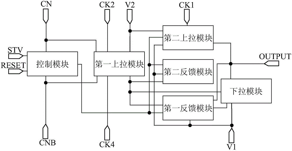
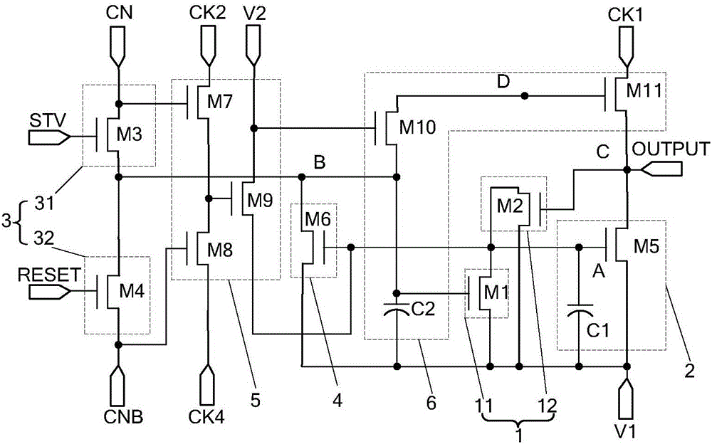
[0027] In view of this, the inventor of the present application provides an improved technical solution, by setting at least two feedback units in the first feedback module, the control terminals of each feedback unit are respectively connected to different control points, and each feedback unit The input terminals of each feedback unit are connected to the first level input terminal, and the output terminals of each feedback unit are connected to the control terminal of the pull-down module, and each feedback unit can independently control the connection between the control terminal of the ...

Embodiment 2

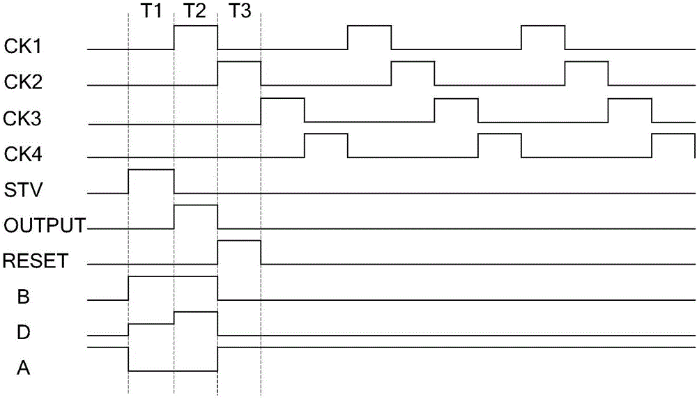
[0046] An embodiment of the present invention provides a driving method of a shift register, the driving method is used to drive the above-mentioned shift register, and the driving method includes:

[0047] Different feedback units included in the first feedback module are controlled through different control points to control the potential of the first node, and the pull-down module is controlled through the first node to control the connection between the first level input terminal and the signal output terminal.

[0048] Since the different feedback units included in the first feedback module are controlled through different control points, and the input end of each feedback unit is connected to the first level input end, and the output end of each feedback unit is connected to the control end of the pull-down module, Each feedback unit can independently control the connection between the control terminal of the pull-down module and the first level input terminal, so even if...


PUM


Abstract

The invention relates to the technical field of display, is applied to providing driving signals for grid lines, and discloses a shift register and a driving method thereof, a grid driving circuit, and a display apparatus, for enhancing the noise-resistance capability of a conventional shift register. The shift register comprises a first feedback module and a pull-down module, wherein the first feedback module comprises at least two feedback units, the control ends of the feedback units are respectively connected with different control points, the input end of each feedback unit is connected with a first level input end, the output end of each feedback unit is connected with a first node, the first node is connected with the control end of the pull-down module, the input end of the pull-down module is connected with the first level input end, and the output end of the pull-down module is connected with the signal output end of the shift register.

Description

technical field [0001] The present invention relates to the field of display technology, in particular to a shift register, a driving method thereof, a gate driving circuit, and a display device. Background technique [0002] At present, a display device generally includes an array substrate and a gate driving circuit, wherein the gate driving circuit is bound on the peripheral area of ​​the array substrate through a flexible circuit board. Specifically, the gate drive circuit includes multi-stage shift registers cascaded with each other, wherein the input terminal of the current-stage shift register is connected to the output terminal of the previous-stage shift register, and the reset control terminal of the current-stage shift register Connect to the output end of the next-stage shift register, and the output end of the current-stage shift register is connected to a gate line on the array substrate; each gate line is controlled to be turned on by each level of shift regis...

Claims


Application Information

Patent Timeline
IPC IPC(8): G09G3/20G11C19/28
CPCG09G3/3677G09G2300/0408G09G2310/0286G09G2310/08G11C19/184G11C19/188G11C19/28
Inventor 王继国
Owner BOE TECH GRP CO LTD
Why Eureka
Try Eureka