Train redundancy dynamic configuration method and system

A technology of dynamic configuration and redundant configuration, applied in the field of train Ethernet, can solve the problem of inability to realize the dynamic configuration redundancy of train network

Active Publication Date: 2015-11-25
KYLAND TECH CO LTD
View PDF2 Cites 7 Cited by
  • Summary
  • Abstract
  • Description
  • Claims
  • Application Information

AI Technical Summary

Problems solved by technology

[0012] The embodiment of the present invention provides a dynamic configuration method and system for train redundancy, which is used to solve the problem in the prior art that the train can only be statically configured with redundancy before the train group leaves the factory, and cannot realize the dynamic configuration redundancy of the train network.

Method used


Image

  • Train redundancy dynamic configuration method and system
  • Train redundancy dynamic configuration method and system
  • Train redundancy dynamic configuration method and system

Examples


Embodiment Construction

[0035] In order to solve the problem of realizing redundant dynamic configuration of backbone switches in the process of train networking, improve the flexibility of train networking, and ensure the reliability of train communication, the present invention provides a redundant dynamic configuration method and system for trains.

[0036] The present invention will be described in detail below in conjunction with the accompanying drawings.

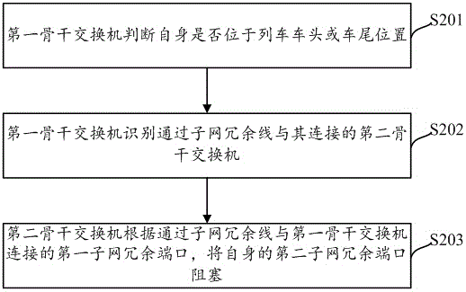
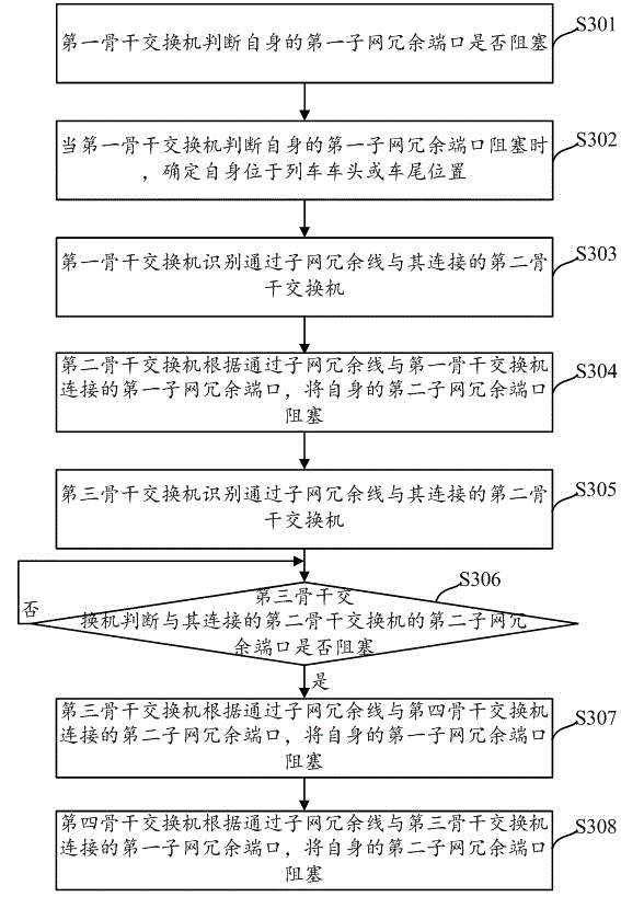
[0037] figure 2 A schematic diagram of a train redundant serial dynamic configuration process provided by an embodiment of the present invention, the process includes the following steps:

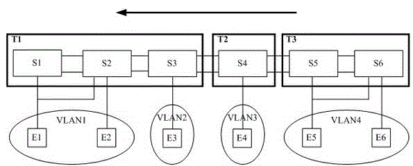
[0038]S201: The first backbone switch determines whether it is located at the front or rear of the train.

[0039] In the embodiment of the present invention, in order to realize the dynamic configuration of the redundancy of each backbone switch of the train, there are subnet redundant lines connected between the backbone switches of the train, and the...


PUM


Abstract

The embodiment of the present invention provides a train redundancy dynamic configuration method and a system. According to the method, a first backbone switch judges whether being located at the headstock/tailstock part of a train or not. When the judgment result of the first backbone switch is yes, the first backbone switch recognizes a second backbone switch connected with the first backbone switch via a subnet redundant line. The second backbone switch blocks off the second subnet redundant port thereof via a first subnet redundant port connected with the first backbone switch via a subnet redundant line. According to the embodiments of the invention, all backbone switches are connected via subnet redundant lines, and the subnet ports of the backbone switches respectively bypass the first subnet redundant port and the second subnet redundant port. Through blocking off one subnet redundant port of the backbone switches, the mutual backup of adjacent backbone switches is realized. Therefore, the redundancy dynamic configuration of the backbone switches is realized, so that the Ethernet reliability of trains is ensured. Meanwhile, the networking flexibility of trains is improved.

Description

technical field [0001] The invention relates to the technical field of train Ethernet, in particular to a method and system for dynamically configuring train redundancy. Background technique [0002] The traditional CAN bus technology can no longer fully meet the information communication requirements of the train. Firstly, the communication rate of the field bus is low, and the amount of information transmitted at one time is small, which cannot meet the transmission requirements of large amounts of information. Secondly, due to the continuous update of equipment, the network topology It is becoming more and more complicated, and the networking flexibility of the field bus is poor; and with the development of train monitoring and detection technology, the field bus cannot meet the requirements of more equipment to communicate with ground equipment. Therefore, with the rapid development of Ethernet technology, industrial Ethernet has replaced the traditional CAN bus and is w...

Claims


Application Information

Patent Timeline
Patent Type & Authority Applications(China)
IPC IPC(8): H04L12/24H04L1/22
Inventor 江启运
Owner KYLAND TECH CO LTD
Why Eureka
Try Eureka