
Three-rotor displacement pump

A volumetric pump and three-rotor technology, which is applied in the field of volumetric pumps, can solve the problems of low flow rate of volumetric pumps, and achieve the effects of increased output flow rate, low cost, and high component utilization

Inactive Publication Date: 2015-12-02
北京工信联创科技有限公司
View PDF7 Cites 1 Cited by
  • Summary
  • Abstract
  • Description
  • Claims
  • Application Information

AI Technical Summary

Problems solved by technology

[0008] The purpose of the present invention is to provide a three-rotor volumetric pump to solve the technical problem of small volumetric pump flow rate in the prior art

Method used

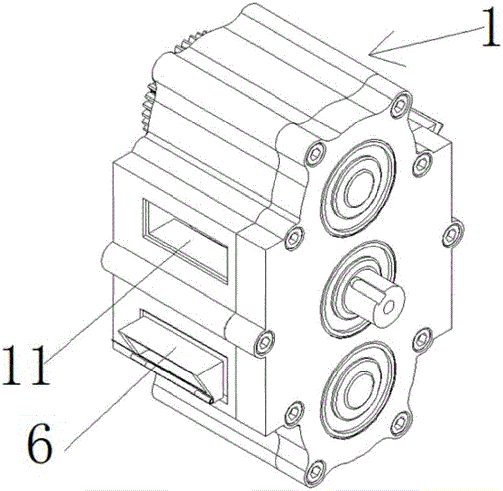
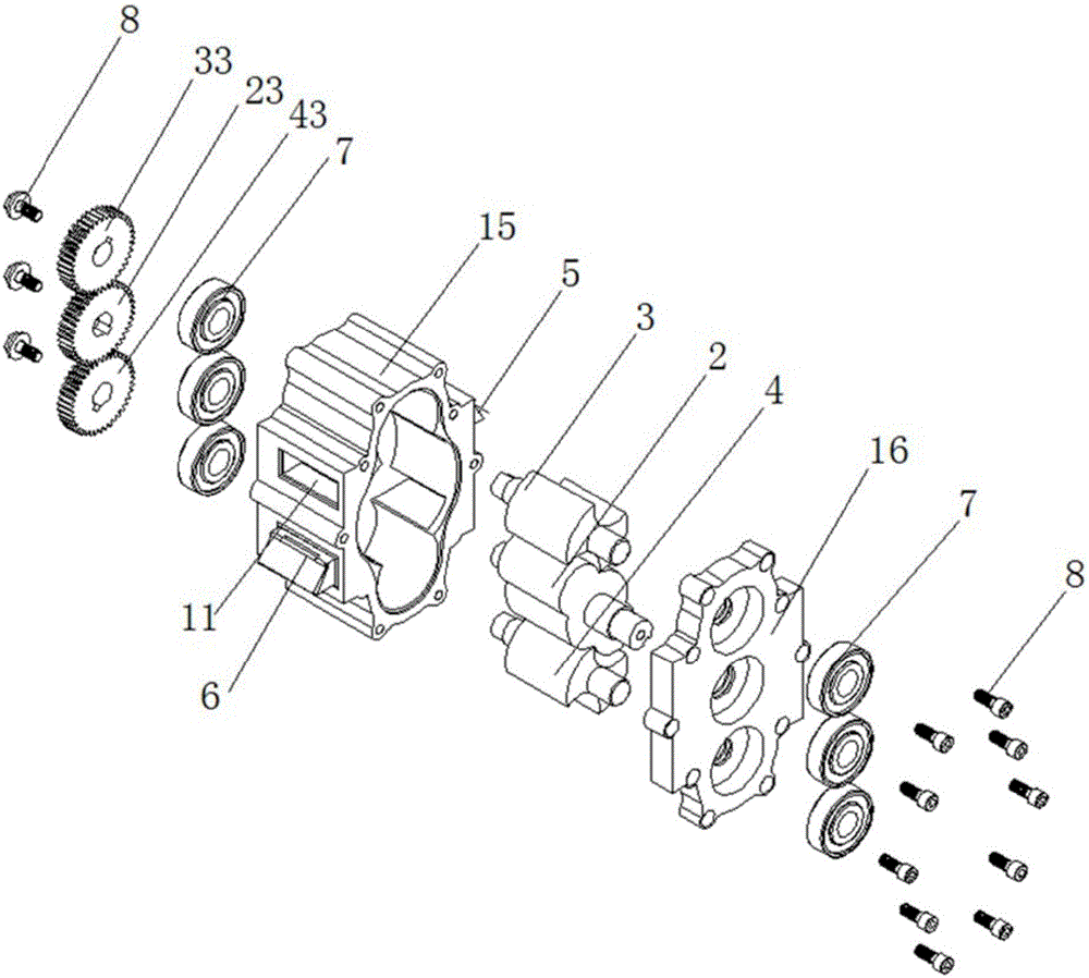
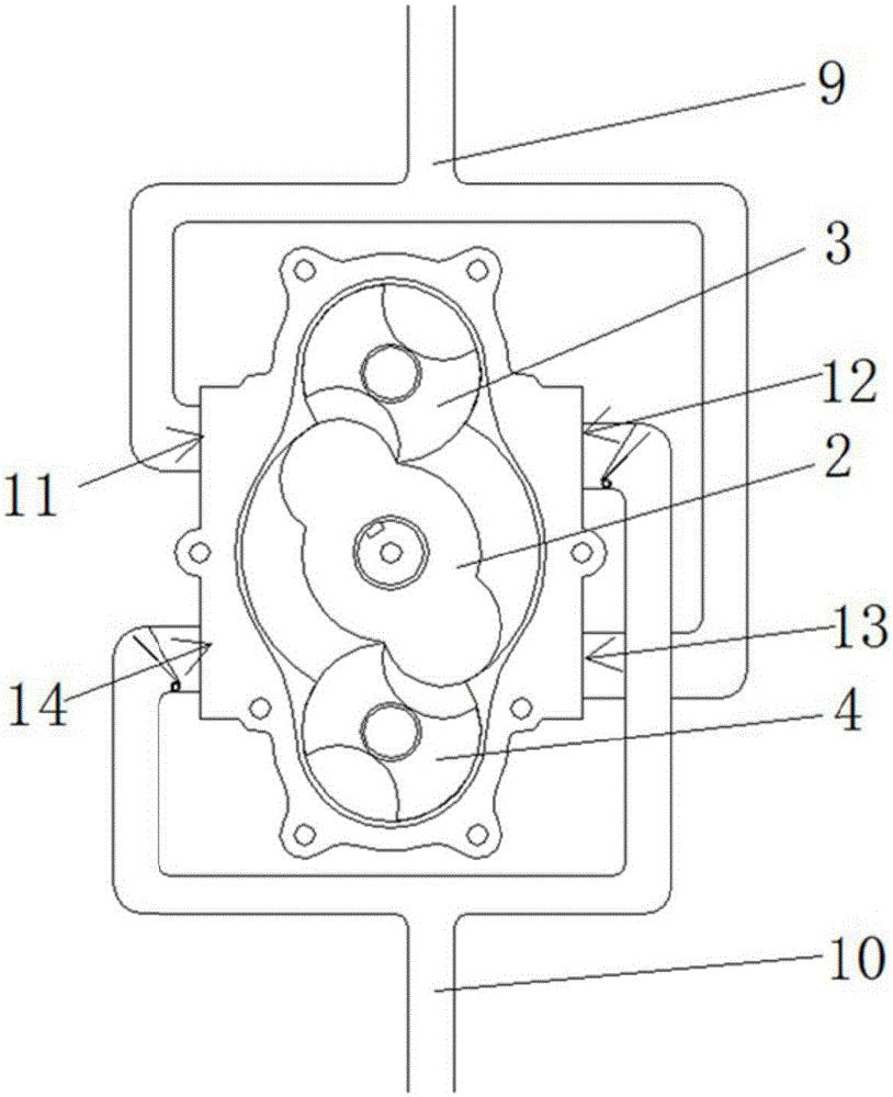

Image

  • Three-rotor displacement pump
  • Three-rotor displacement pump
  • Three-rotor displacement pump

Examples


Embodiment Construction

[0050] The technical solutions of the present invention will be clearly and completely described below in conjunction with the accompanying drawings. Apparently, the described embodiments are some of the embodiments of the present invention, but not all of them. Based on the embodiments of the present invention, all other embodiments obtained by persons of ordinary skill in the art without making creative efforts belong to the protection scope of the present invention.

[0051] In the description of the present invention, it should be noted that the terms "center", "upper", "lower", "left", "right", "vertical", "horizontal", "inner", "outer" etc. The indicated orientation or positional relationship is based on the orientation or positional relationship shown in the drawings, and is only for the convenience of describing the present invention and simplifying the description, rather than indicating or implying that the referred device or element must have a specific orientation, ...


PUM


Abstract

The invention relates to the technical field of displacement pumps and particularly relates to a three-rotor displacement pump. The three-rotor displacement pump comprises a pump shell, wherein a main rotor, a first secondary rotor and a second secondary rotor are arranged in the pump shell; the first secondary rotor and the second secondary rotor are arranged at two sides of the main rotor and can be in contact with the main rotor all the time; the first secondary rotor and the second secondary rotor are in contact with the inner wall of the pump shell all the time in the rotation process; a first liquid inlet, a first liquid outlet, a second liquid inlet and a second liquid outlet are formed in the outer wall of the pump shell in sequence; the first liquid inlet and the first liquid outlet are formed in one side of the main rotor; the second liquid inlet and the second liquid outlet are formed in the other side of the main rotor; the first liquid inlet and the first liquid outlet are formed in two sides of the first secondary rotor respectively; the second liquid inlet and the second liquid outlet are formed in two sides of the second secondary rotor respectively. Through the three-rotor displacement pump, the liquid is sucked and discharged for four times by the pump when the main rotor rotates a circle; both the output flow and the working efficiency of the pump are improved.

Description

technical field [0001] The invention relates to the technical field of displacement pumps, in particular to a three-rotor displacement pump. Background technique [0002] Positive displacement pumps refer to pumps that use the change in the volume of the pump cylinder to transport liquid, such as reciprocating pumps, rotor pumps, etc. [0003] Reciprocating pump: [0004] A reciprocating pump is a pump that uses the reciprocating motion of the piston to transport the liquid, and the energy is directly transmitted in the form of static pressure energy by the reciprocating motion of the piston. Since the liquid is incompressible, when the piston presses the liquid, the liquid can be subjected to a high pressure, thereby obtaining a high lift. [0005] Rotor pump: [0006] The rotor pump is composed of a stationary pump casing and a rotating rotor. The side of the rotor in the pump body in contact with the liquid directly acts on the liquid in the form of static pressure, an...

Claims


Application Information

Patent Timeline
Patent Type & Authority Applications(China)
IPC IPC(8): F04C2/14F04C15/06
Inventor 陈洪亮李贺
Owner 北京工信联创科技有限公司
Learn More