
Novel valve

A valve, a new type of technology, applied in valve details, safety valves, balance valves, etc., can solve problems such as increasing production costs, increasing energy consumption of water pumps, and failure to achieve normal irrigation

Active Publication Date: 2015-12-02
乐清市兴丰电子厂
View PDF6 Cites 5 Cited by
  • Summary
  • Abstract
  • Description
  • Claims
  • Application Information

AI Technical Summary

Problems solved by technology

[0005] For the above-mentioned existing agricultural irrigation valves, the applicant found that there are still deficiencies in the use process. For large-scale agricultural irrigation, a first high-power water pump and a main irrigation pipeline are now provided, and the main pipeline is connected to many branch valves. The above-mentioned valves are installed at the nodes of the pipeline, the main pipeline and the sub-pipes. The fluid pressure of the main pipeline is gradually dispersed by the sub-pipes and the extension of the pipeline, and the fluid pressure gradually decreases. For the valves at the rear nodes, the fluid pressure value used for opening It is still much smaller than the pressure at the front node, which makes the valve at the rear node may not be able to achieve the purpose of opening due to the small pressure used to make it open, and normal irrigation cannot be achieved, that is, F1

Method used


Image

  • Novel valve
  • Novel valve
  • Novel valve

Examples


Embodiment Construction

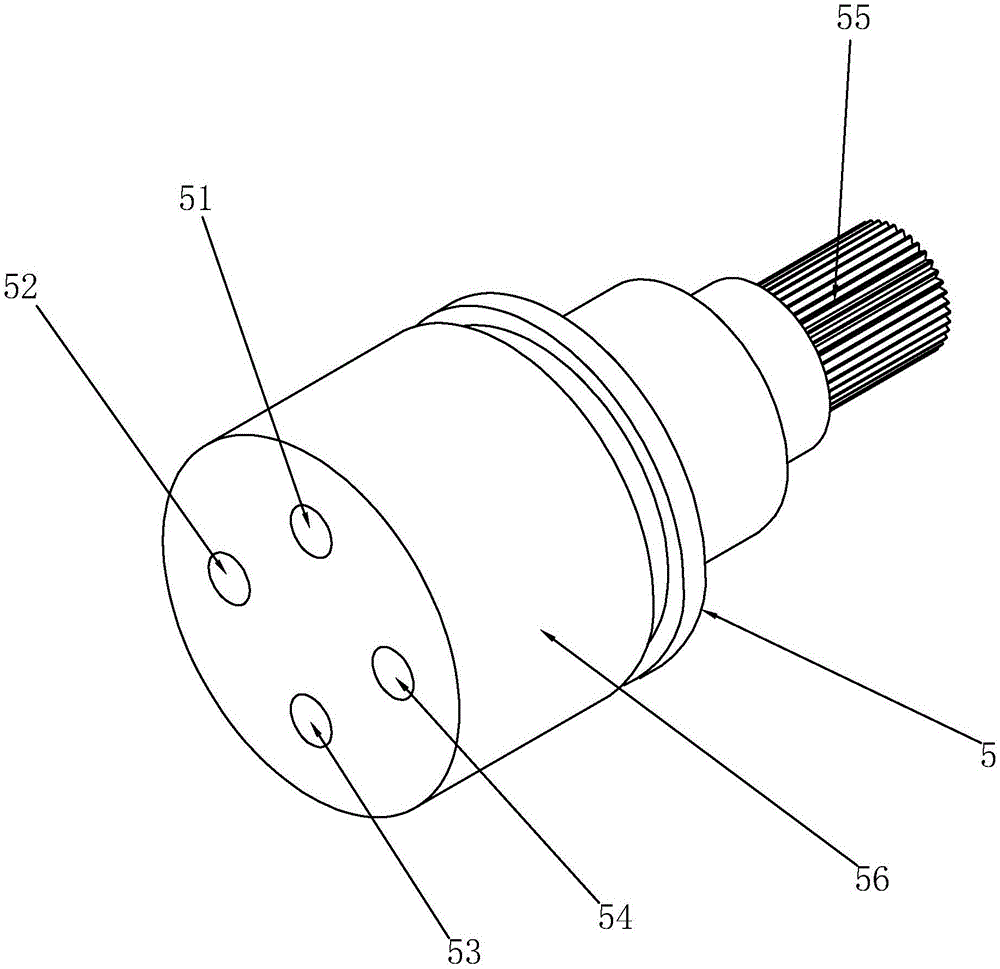
[0037] refer to Figure 1 to Figure 9 The embodiments of the present invention will be further described.

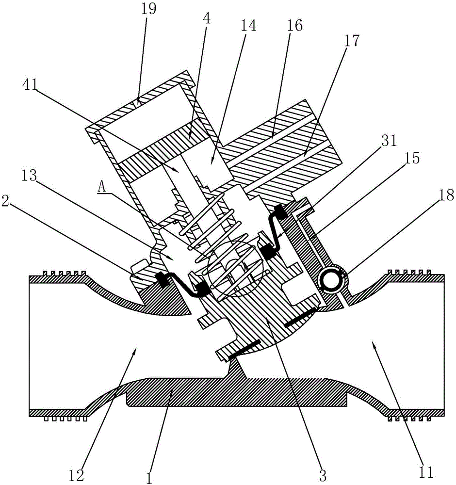
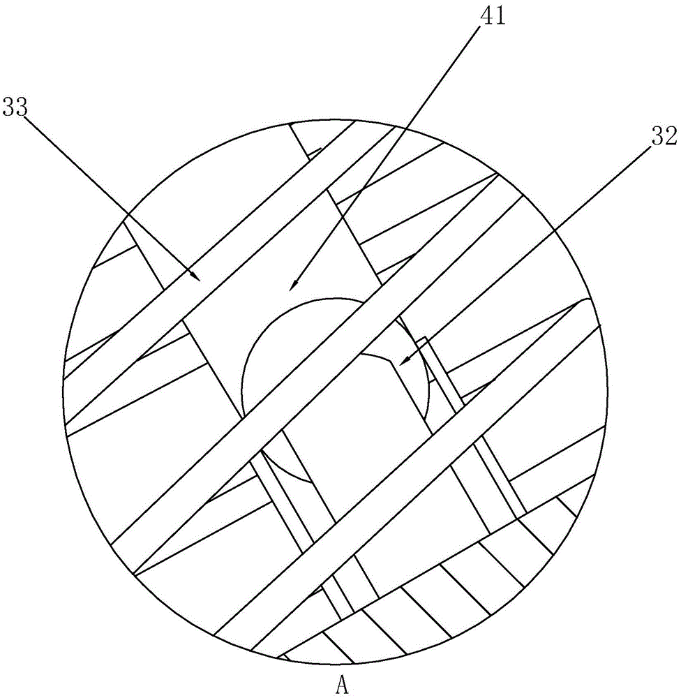
[0038] The novel valve described in this embodiment, such as figure 1 As shown, it includes a valve body 1, the valve body 1 includes a valve cover 2, the valve body 1 has a water inlet channel 11, a water outlet channel 12 and a valve cavity for installing a valve core 3, and the valve core 3 is used to communicate with the valve body 1 The valve seat interferes to block the water inlet channel 11 and the water outlet channel 12. The valve core 3 includes an elastic member and is always in contact with the valve seat by means of the elastic member. The elastic member in the prior art uses a spring 33, and the spring 33 is also used in this embodiment. , for convenience. An elastic diaphragm 31 is also connected between the valve core 3 and the inner wall of the valve cavity, and the elastic diaphragm 31 separates the valve cavity into an upper cavity 13 and a lower ca...


PUM


Abstract

The invention discloses a novel valve. The novel valve comprises a valve body which comprises a valve bonnet and is provided with a water inlet channel, a water outlet channel and a valve cavity for mounting of a valve core. The valve core is used for abutting against a valve seat in the valve body to block the water inlet channel and the water outlet channel. The valve core comprises an elastic part and abuts against the valve seat by the aid of the elastic part throughout. An elastic membrane is further connected between the valve core and the inner wall of the valve cavity and divides the valve cavity into an upper cavity body and a lower cavity body. An auxiliary opening device is further arranged on the valve body and comprises an auxiliary valve cavity formed in the valve body. A pulling part for pulling the valve core is arranged in the auxiliary valve cavity and connected with the valve core. The pulling part is driven by fluid entering the auxiliary valve cavity. The novel valve further comprises a switching assembly. A main water inlet way is arranged between the water inlet channel and the switching assembly. The switching assembly is used for controlling water inlet of the auxiliary valve cavity and water outlet of the upper cavity body, or water inlet of the upper cavity body and water outlet of the auxiliary valve cavity. By means of the novel valve, low-pressure opening can be achieved, and energy consumption of an irrigation system is lowered.

Description

technical field [0001] The present invention relates to a valve, more specifically it relates to an agricultural irrigation valve. Background technique [0002] Agricultural irrigation valves are widely used in large-scale agricultural irrigation, and the valve mainly plays the role of on-off of multiple irrigation pipelines. [0003] In the prior art, the applicant’s recent patent document with application number 201520091060.9 discloses a valve using a valve switch assembly, including a valve body with an inner cavity, and a water inlet channel and an outlet channel are opened in the valve body , the inner cavity is provided with a movable elastic diaphragm, and the elastic diaphragm divides the inner cavity into an upper cavity and a lower cavity, and the valve body also includes a valve switch assembly and a mounting base. The installation base is provided with the water inlet and outlet of the upper cavity, the water inlet and the emptying port of the upper cavity, and...

Claims


Application Information

Patent Timeline
IPC IPC(8): F16K17/10F16K31/126
CPCF16K17/10F16K31/1262
Inventor 黄锋黄正清
Owner 乐清市兴丰电子厂
Learn More