Paper currency recognition device

A banknote identification and banknote technology, which is applied in the field of internal components of cash automatic teller machines, can solve problems such as deterioration of product yield, relative position offset, loose and fatigue parts, etc., to achieve easy disassembly, maintenance and cleaning, easy positioning, and strengthening The effect of stability

Active Publication Date: 2015-12-02
SHANGHAI GOOAO ELECTRONIC TECHNOLOGY CORP
View PDF6 Cites 1 Cited by
  • Summary
  • Abstract
  • Description
  • Claims
  • Application Information

AI Technical Summary

Problems solved by technology

However, if the mounting error of the supporting member relative to the supporting base material is large, that is, if the dimensional tolerance is large, there will be such a problem that the output level of the sensor will vary, and the variation in the recognition performance of the device will increase. , The product yield deteriorates, and the recognition results are prone to errors
[0004] This technical solution divides the upper supporting mechanism into two parts, which can be opened in a pin-connected manner, so that functions such as maintenance and cleaning can be easily realized, but it is still the same as the upper and lower supporting mechanisms in the prior art, and it is easy to work for a long time. Afterwards, the parts are loose and fatigued, or the relative position between the upper and lower support mechanisms is shifted due to the continuous operation of the roller shaft and other parts, which affects the recognition accuracy between the upper and lower parts of the sensor group installed on it, which is not conducive to the identification of banknotes. accurate identification of

Method used


Image

  • Paper currency recognition device
  • Paper currency recognition device
  • Paper currency recognition device

Examples


Embodiment Construction

[0027] Hereinafter, embodiments of the present invention will be described with reference to the drawings. In the embodiments, parts of the same configuration are given the same reference numerals and descriptions are omitted.

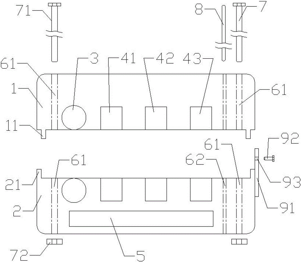
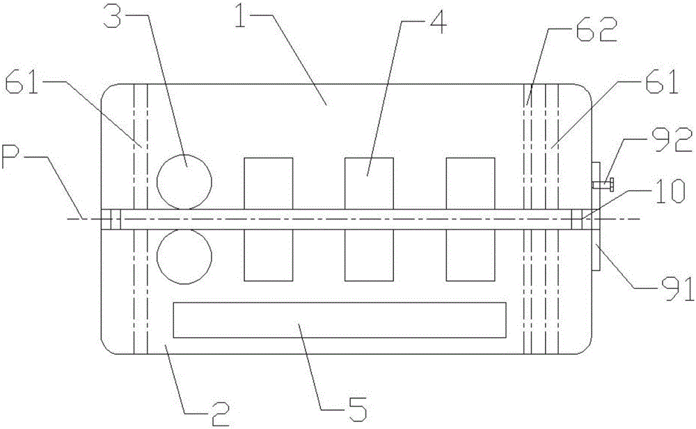
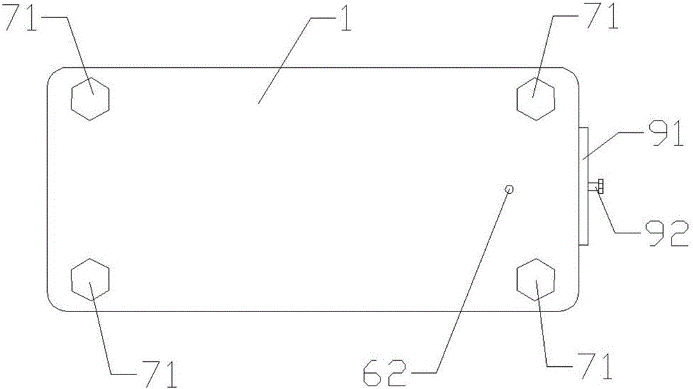
[0028] refer to figure 1 , is a schematic diagram of the exploded structure of the banknote identification device of the present invention; figure 2 , is a schematic diagram of the combination of the upper support mechanism and the lower support mechanism of the banknote identification device of the present invention; and image 3 , is a top structural schematic view of the banknote identification device of the present invention. As shown in the figure, the banknote identification device is installed in a cash automatic teller machine (ie ATM) to identify the banknotes passing along the banknote conveying path P and to identify their authenticity, and the banknotes The identification device includes an upper supporting mechanism 1 , a lower support...


PUM


Abstract

The invention discloses a paper currency recognition device arranged in an ATM, which comprises an upper support mechanism, a lower support mechanism, transport rollers, a sensor group, a controller, bolt-nut assemblies, a fine tuning panel, and a fine tuning bolt. The upper support mechanism and the lower support mechanism are combined and the combination surface of the upper support mechanism and the lower support mechanism is provided with a paper currency transport path channel. The transport rollers are located on the two sides of the paper currency transport path channel. The controller receives the characteristics of paper currency that are detected by the sensor group, then recognizes the species of the paper currency and distinguishes the authenticity of the paper currency. A plurality of fixed screw holes symmetrically pass through the interiors of the upper and lower support mechanisms. The bolt-nut assemblies are arranged inside the fixed screw holes. The side surface of the lower support mechanism is fixedly connected with the fine tuning panel. The fine tuning panel is provided with a threaded hole. The fine tuning bolt is penetrated through the threaded hole. According to the technical scheme of the invention, the operation stability of the device is reinforced. In this way, the detecting deviation phenomenon caused by the deviation between the upper and lower parts of the sensor group is hard to occur. Therefore, all parts of the sensor group can be aligned at a high precision, so that more accurate measurement values can be obtained.

Description

technical field [0001] The invention relates to the field of internal components of cash automatic teller machines, in particular to a banknote identification device. Background technique [0002] A banknote handling device such as an automatic teller machine (ATM) is equipped with a sensor for specifying the number of banknotes to be deposited or withdrawn, and to determine the denomination and authenticity of the banknotes. In the current technology, this type of sheet recognition device with sensors often includes a support member pivotally supported relative to the support base through a conveyance path, and sensors are attached to the support member and the support base. During the maintenance work, the support member is rotated relative to the support base to expose the conveyance path to the outside in order to remove banknotes or foreign objects remaining in the conveyance path and to facilitate maintenance such as cleaning of the sensor surface. However, if the mou...

Claims


Application Information

Patent Timeline
Patent Type & Authority Applications(China)
IPC IPC(8): G07D7/16G07D7/04G07D7/12
Inventor 陈崇军吴刚陈仕云
Owner SHANGHAI GOOAO ELECTRONIC TECHNOLOGY CORP
Why Eureka
Try Eureka