Buffering and cooling electric vehicle battery containing structure

A battery and battery placement technology for electric vehicles, applied to secondary batteries, structural parts, battery pack parts, etc., can solve problems such as no buffer device, soaring battery box temperature, battery explosion, etc., to improve safety and improve use The effect of longevity

Active Publication Date: 2015-12-02
SUZHOU JOYDEER E BICYCLE
View PDF4 Cites 24 Cited by
  • Summary
  • Abstract
  • Description
  • Claims
  • Application Information

AI Technical Summary

Problems solved by technology

[0002] At present, electric vehicles have been very popular in China. Due to their convenient charging and simple operation, they have replaced bicycles in people's status. However, electric vehicles need electricity as power, that is, they must be powered by batteries, and the existing batteries It is installed in the battery box, and the battery box is fixed in the battery slot on the frame. It is generally fixedly connected, so that when the car vibrates, the battery box will also vibrate, and because the battery box is hard-connected to the car In the frame, there is no other buffer device. After a long time, it will have an impact on the use of the battery. It is easy to make the connecting wires welded in the battery detached, making the electric car unable to open and affecting the use. Moreover, there is no What kind of ventilated structure, when the electric vehicle is used and charged, the temperature in the battery box will soar, and when the old battery is used for a long time, it will cause safety hazards such as explosion due to excessive temperature

Method used


Image

  • Buffering and cooling electric vehicle battery containing structure
  • Buffering and cooling electric vehicle battery containing structure

Examples


Embodiment Construction

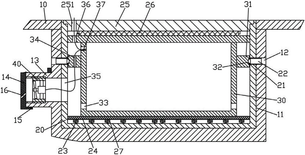
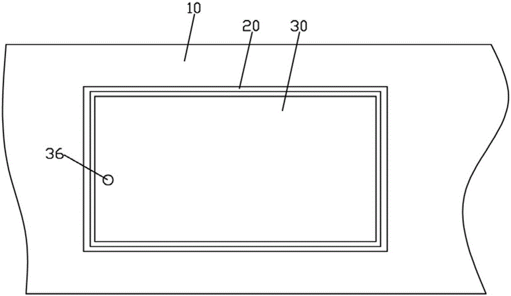
[0015] Examples, see e.g. Figures 1 to 2 As shown, a buffer cooling electric vehicle battery placement structure includes a vehicle frame 10, the middle part of the vehicle frame 10 has a battery placement groove 11, and a battery box protective shell 20 is inserted and fixed in the battery placement groove 11, and the battery box protection There are multiple screw through holes 21 on the side wall of the shell 20, and there are also multiple through holes 12 on the side wall of the battery placement groove 11. The through holes 12 correspond to the screw through holes 21 one by one, and the ball plunger 22 is screwed. Connected to the screw through hole 21, the battery box 30 is placed in the battery box protective case 20, the outer wall of the middle part of the battery box 30 has an annular positioning part 31, and the steel ball of the ball plunger 22 is nested in the annular positioning part 31 In the recessed hole 32 on the top, there is a fan connecting cylinder 13 o...


PUM


Abstract

The invention discloses a buffering and cooling electric vehicle battery containing structure which comprises a frame. A battery containing groove is formed in the middle of the frame, a battery box protection shell is fixedly inserted into the battery containing groove in a sleeved mode, multiple threaded connection through holes are formed in the side walls of the battery box protection shell, ball-head plungers are connected into the threaded connection through holes in a threaded mode, and a battery box is put into the battery box protection shell; the outer side walls of the middle of the battery box are each provided with an annular positioning portion, steel balls of the ball-head plungers are nested in concave holes formed in the annular positioning portions, the outer side wall of the battery containing groove is provided with a fan connecting cylinder, an exhaust fan is connected in the fan connecting cylinder in a threaded mode, multiple buffer springs are fixed to the bottom face of the battery box protection shell, a buffer cushion is put on the buffer springs, and the battery box abuts against the buffer cushion in a pressing mode, so that when an electric vehicle runs, a buffer effect on the battery box is achieved, and the service life is prolonged; meanwhile, by means of the exhaust fan, certain heat in the battery box can be exhausted, and the safety is improved.

Description

Technical field: [0001] The invention relates to the technical field of electric vehicle equipment, and more specifically relates to a battery placement structure for buffering and cooling electric vehicles. Background technique: [0002] At present, electric vehicles have been very popular in China. Due to their convenient charging and simple operation, they have replaced bicycles in people's status. However, electric vehicles need electricity as power, that is, they must be powered by batteries, and the existing batteries It is installed in the battery box, and the battery box is fixed in the battery slot on the frame. It is generally fixedly connected, so that when the car vibrates, the battery box will also vibrate, and because the battery box is hard-connected to the car In the frame, there is no other buffer device. After a long time, it will have an impact on the use of the battery. It is easy to make the connecting wires welded in the battery detached, making the ele...

Claims


Application Information

Patent Timeline
Patent Type & Authority Applications(China)
IPC IPC(8): H01M2/10H01M10/613H01M10/625H01M10/6563H01M50/242H01M50/244H01M50/249
CPCH01M50/24H01M50/20Y02E60/10
Inventor 蓝瀚丁明燕
Owner SUZHOU JOYDEER E BICYCLE
Why Eureka
Try Eureka