Multifunctional socket structure

A multi-function, socket technology, applied in the base/shell, parts of the connecting device, coupling devices, etc., can solve the problems of insufficient intelligence, trouble, single function, etc., and achieve easy and flexible use, convenient use, and strong convenience. Effect

Pending Publication Date: 2015-12-02
ZHONGSHAN KINGRONG ELECTRONICS CO LTD
View PDF0 Cites 2 Cited by
  • Summary
  • Abstract
  • Description
  • Claims
  • Application Information

AI Technical Summary

Problems solved by technology

[0002] The socket is one of the most commonly used devices for connecting electrical equipment to the power supply. With the rapid development of information technology and technology, there are more and more high-tech electronic equipment such as mobile phones, MP3, PSP, and tablet computers. Especially mobile phones, almost Everyone has it, and these powered devices need electricity. The existing charging method is generally to insert the charging cable into the jack of the socket for wired charging, and because the existing socket only has a jack, Generally, it does not have the function of storage and storage, and the function is single. Users need to find a space near the socket to place the powered device. Every time they charge, they need to find a space to place the mobile phone, which is troublesome.
In addition, the existing power receiving equipment can generally only be plugged into the socket for wired charging through the charging cable. The charging method is single, and the function of the socket is also very single. Moreover, the existing socket structure is traditional and old, not flexible enough to use, and not smart enough. change

Method used


Image

  • Multifunctional socket structure
  • Multifunctional socket structure
  • Multifunctional socket structure

Examples


Embodiment Construction

[0020] It should be understood that the specific embodiments described here are only used to explain the present invention, not to limit the present invention.

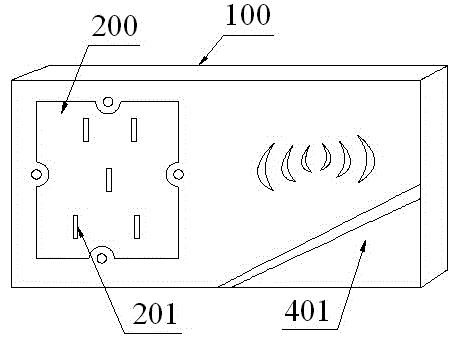
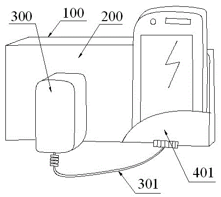
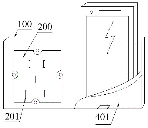
[0021] refer to Figure 1 to Figure 9 , an embodiment of a multi-functional socket structure of the present invention is proposed, including a strip-shaped bottom shell 100 that can be installed horizontally or vertically on the wall, adapted to the bottom shell 100 and covered on the bottom shell 100 The panel 200, the circuit module set in the bottom case 100, and a plurality of jacks 201 set on the panel 200, the jacks 201 can be inserted into the plug 300 and electrically connected with the circuit module.

[0022] The socket is one of the most commonly used devices for connecting electrical equipment to the power supply. With the rapid development of information technology and technology, there are more and more high-tech electronic equipment such as mobile phones, MP3, PSP, and tablet computers. Especially mobil...


PUM


Abstract

The invention discloses a multifunctional socket structure, which comprises a bottom shell, a panel covering the bottom shell, a circuit module arranged inside the bottom shell, and a plurality of jacks arranged in the panel, wherein the jacks can enable a plug to be inserted inside the socket and the plug is electrically connected with the circuit module; and the panel is provided with a bearing structure which can bear an object, and a power receiving device can be placed on the bearing structure and can be inserted in the jack via a charging line for being changed in a wired mode. The socket structure also comprises a wireless charging device corresponding to the bearing structure in the aspect of positions; the power receiving device is placed on the bearing structure and is wirelessly charged via the wireless charging device; the wireless charging device comprises a power supply transmission module, a power receiving module and a wireless power transmission structure; the power supply transmission module is arranged inside the bottom shell, is corresponding to the bearing structure in the aspect of positions and is electrically connected with the circuit module; the power receiving module is arranged on the power receiving device and can receive power of the power supply transmission module so as to charge the battery of the power receiving device; and the wireless power transmission structure can wirelessly transmit power between the power supply transmission module and the power receiving module.

Description

technical field [0001] The invention relates to the technical field of electrical sockets, in particular to a multifunctional socket structure. Background technique [0002] The socket is one of the most commonly used devices for connecting electrical equipment to the power supply. With the rapid development of information technology and technology, there are more and more high-tech electronic equipment such as mobile phones, MP3, PSP, and tablet computers. Especially mobile phones, almost Everyone has it, and these powered devices need electricity. The existing charging method is generally to insert the charging cable into the jack of the socket for wired charging, and because the existing socket only has a jack, Generally, it does not have the function of storage and storage, and the function is single. Users need to find a space near the socket to place the powered device. Every time they charge, they need to find a space to place the mobile phone, which is troublesome. ...

Claims


Application Information

Patent Timeline
IPC IPC(8): H01R13/46H01R13/66H01R13/717H02J7/02H02J17/00
Inventor 朱春常
Owner ZHONGSHAN KINGRONG ELECTRONICS CO LTD
Why Eureka
Try Eureka