Driving debugging tool

A technology for debugging tooling and debugging board, applied in the field of mechanical tooling, can solve problems such as meeting the standard and not being able to determine the performance of the optical part well, and achieve the effect of reducing the impact

Inactive Publication Date: 2015-12-02
WUHAN RAYCUS FIBER LASER TECHNOLOGY CO LTD
View PDF6 Cites 0 Cited by
  • Summary
  • Abstract
  • Description
  • Claims
  • Application Information

AI Technical Summary

Problems solved by technology

[0002] In the actual production process of the laser, there is a process of assembling the electrical and optical parts separately. It is impossible to determine whether the performance of the optical part is up to standard before assembly. In order to make a preliminary judgment on the optical part, it needs to be tested during the optical production process. In the process, an adjustable frequency drive is provided for the pulsed laser acousto-optic to verify whether there is a problem with the optical path. Therefore, it is necessary to invent a driving and debugging tool with a reasonable structure, good heat dissipation and easy operation.

Method used


Image

  • Driving debugging tool

Examples


Embodiment Construction

[0014] In order to make the object, technical solution and advantages of the present invention clearer, the embodiments of the present invention will be further described in detail below in conjunction with the accompanying drawings.

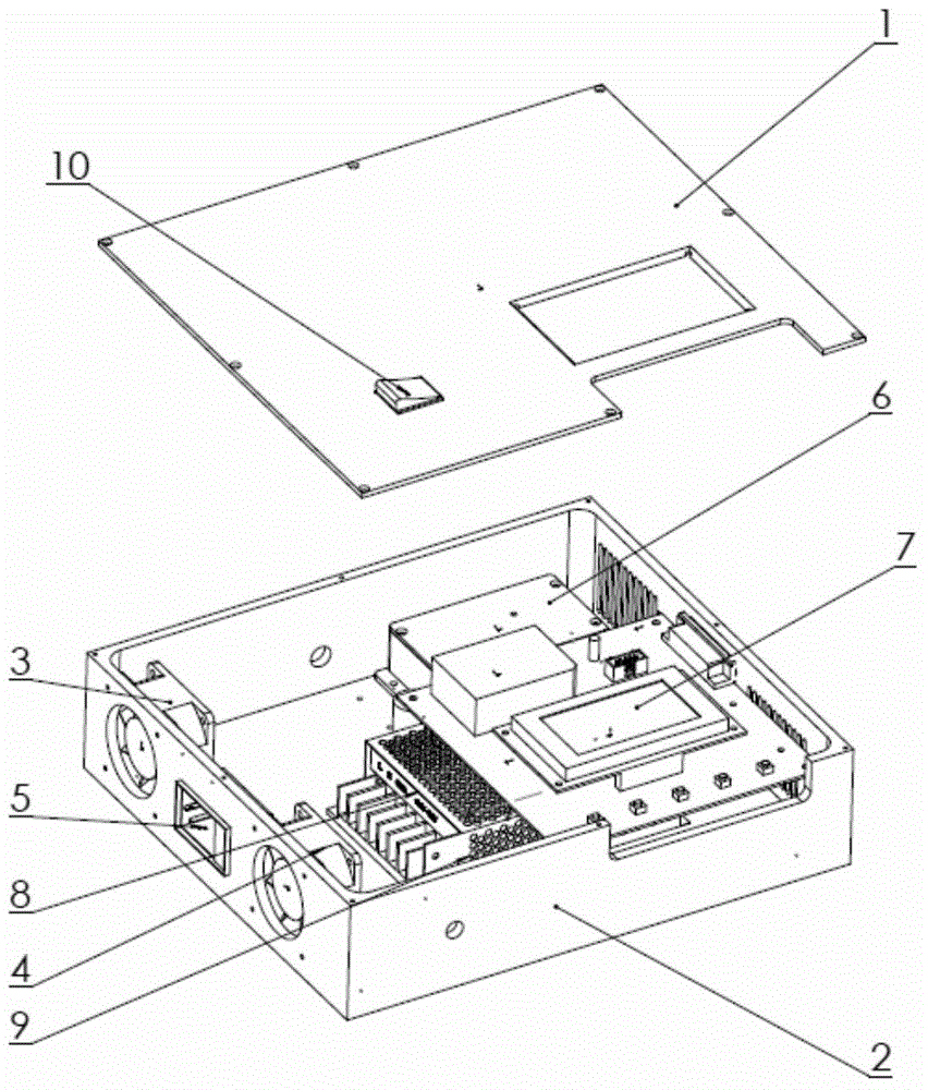
[0015] Such as figure 1 As shown, the present invention is composed of a debugging board 7, a housing 2, a driver I6, a driver II9, two fans (3, 4), a power socket 5, a double-pole double-throw switch 10, a switching power supply 8, and a cover plate 1. It is characterized in that: the cover plate 1 is covered and fixed on the bottom case 2; the power socket 5 is fixed on the bottom case 2 by buckling; two fans (3, 4), driver I6, debugging board 7, switching power supply 8. The drive II 9 is respectively fixed on the bottom case 2; the switching power supply 8 is respectively connected to the two fans (3, 4), the power socket 5, and the debugging board 7 through wires to form a circuit, and the two fans (3, 4) are In parallel connection, driver...


PUM


Abstract

The present invention relates to a driving debugging tool, wherein the structure of the driving debugging tool is that: a cover plate covers and is fixed on a bottom shell; a power socket is fixed on the bottom shell through a snap joint mode; two fans, a driving I, a debugging board card, a switching power supply and a driving II are fixed on the bottom shell; and the switching power supply is connected with the two fans through wires, the power socket and the debugging board card form a loop, the two fans are connected in parallel, and the driving I and the driving II are connected with the debugging board card through a double-pole-double-throw switch to form two loops. Different pulse signals may be output by an acousto-optic modulator by means of changing the frequency of the driving through the debugging board card, and the fans are configured to dissipate heat in the shell. According to the invention, the driving debugging tool may be able to realize the requirement for the practical test in production when a laser is only provided with an optical part, and realize the switching of the driving between multi frequency through the double-pole-double-throw switch so that the relative frequency required by the test may be provided and the purpose of testing the performance of the laser is achieved.

Description

technical field [0001] The invention relates to the field of mechanical tooling, in particular to a driving debugging tooling. Background technique [0002] In the actual production process of the laser, there is a process of assembling the electrical and optical parts separately. It is not possible to determine whether the performance of the optical part is up to standard before assembly. In order to make a preliminary judgment on the optical part, it is necessary to test in the optical production process. In the acousto-optic pulse laser, an adjustable frequency drive is provided to verify whether there is a problem with the optical path. Therefore, it is necessary to invent a driving and debugging tool with reasonable structure, good heat dissipation and easy operation. Contents of the invention [0003] In order to quickly and accurately adjust the frequency of the drive, ensure long-term operation, reduce the influence of temperature on the drive, and facilitate switc...

Claims


Application Information

Patent Timeline
IPC IPC(8): H01S3/04G01M11/02
Inventor 谢良虞俊伟李星
Owner WUHAN RAYCUS FIBER LASER TECHNOLOGY CO LTD
Why Eureka
Try Eureka